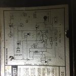
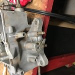
Vac and choke help please

Disclaimer: Links on this page pointing to Amazon, eBay and other sites may include affiliate code. If you click them and make a purchase, we may earn a small commission.

Jneeld

New member
Joined
Oct 17, 2016
Messages
38
Reaction score
0
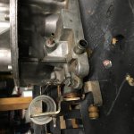
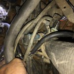
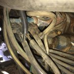
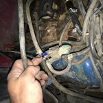
Trying to sort through the mess of vacuum lines and can't really understand the diagram can someone please help me with these parts and tell me what they are. Well it won't let me upload pictures but one of them is a tree and it goes in right where the water line goes in on top of the intake. My ride is a 1980 bronco with the 351 m. I really can't tell what is what on the diagram I've tried searching names of the parts but haven't gotten many pictures and the hoses don't seem to match what is on the diagram.

The next thing is the choke. I can't get the choke to "load" when pressing the gas pedal before cold starting. The choke never moves.


Seabronc

New member
Joined
May 22, 2004
Messages
7,315
Reaction score
35
Location
North of NYC
Will need those pictures, plus one of the vacuum diagram you are working with.  Use the "More Reply Options" on the bottom left to get you in a place that allows uploading pictures.

:)>-

 
OP
OP
J

Jneeld

New member
Joined
Oct 17, 2016
Messages
38
Reaction score
0
Will need those pictures, plus one of the vacuum diagram you are working with.  Use the "More Reply Options" on the bottom left to get you in a place that allows uploading pictures.

:)>-
It's saying images are to big. How do I make them smaller

 
OP
OP
J

Jneeld

New member
Joined
Oct 17, 2016
Messages
38
Reaction score
0
To make sure I'm understanding this right I should step on the gas pedal and the choke should close correct?


Seabronc

New member
Joined
May 22, 2004
Messages
7,315
Reaction score
35
Location
North of NYC
To make sure I'm understanding this right I should step on the gas pedal and the choke should close correct?
Let's cover the choke problem first.  The answer to your question is yes and no. It should close if it was open in the first place.  From the little I can see in your picture, it is closed.   As the engine is warming up from cold, it will gradually open until it is full open.  That is if the choke heat coil and linkage are functioning properly. 

You can resize your pictures using a photo processing program.  No larger than 1024 x 768 pixels so it will fully display on a normal screen without the necessity of moving all around the picture in order top see everything that is on it.  Unfortunately this forum doesn't automatically resize for you so you need to do that ahead of time.  Alternately, you can adjust your camera to take that size picture in the first place.

Another thing I can see in the pictures at FSB is open vacuum ports on your carb.  plus a disconnected transmission kick down linkage. 

:)>-


Seabronc

New member
Joined
May 22, 2004
Messages
7,315
Reaction score
35
Location
North of NYC
Take a look at the picture in post #15 of this link for definitions of vacuum components http://broncozone.com/topic/25497-******-351-windsor-4v-ready-to-go-into-1984-bronco-xlt-to-emission-or-not/

:)>-


Seabronc

New member
Joined
May 22, 2004
Messages
7,315
Reaction score
35
Location
North of NYC
For your convenience I have added a diagram here.  It is not one relevant to your truck, but the definitions will help you understand what the vacuum components are.

VacDef copy.jpg

 
Last edited by a moderator:
OP
OP
J

Jneeld

New member
Joined
Oct 17, 2016
Messages
38
Reaction score
0
For your convenience I have added the diagram here. It is not one relevant to your truck, but the3 definitions will help you understand what the vacuum components are.
Thanks for your help. The choke was closed because I pushed it close with my finger. It won't move at all in relation to the throttle is there a linkage I'm missing or something. Sorry I'm taking the pictures with my phone I'll try and fix it tonight. Yes the lockdown lever is unhooked. Do you know what lines run to those vacuum ports on the back of the carb. The one on the driver side rear has a lot of suction on it while the engine is running. I'm more of a picture guy than a definition lol. I'm just trying to figure out what all is missing.


Seabronc

New member
Joined
May 22, 2004
Messages
7,315
Reaction score
35
Location
North of NYC
There is a linkage, but not one that moves the choke every time you operate the gas pedal.  If the engine is cold, it should trip the linkage of the choke to close it.  Once the engine warms up the choke will be full open and will stay that way as long as the carb is warm.  In other words, the position of the choke, once it is set up properly, will be dependent on the heat coil in the choke.  So if the engine is already warm when you start it, the choke should not completely close.  It will only move back to a position that is dependent on the heat coil.

Those open ports on the carb should have something hooked to them. From the look of the picture and your vacuum diagram, one should be connected to the rear vacuum tree.  Where is the brake vacuum booster connected?  More pictures would be a big help in order to see what hooked to what.

:)>-

 
Last edited by a moderator:

Seabronc

New member
Joined
May 22, 2004
Messages
7,315
Reaction score
35
Location
North of NYC
Let's just talk about the vacuum diagram. As you can see, yours is orientated with the front of the engine on the left.  Components of the diagram are pretty much where you will find them on the engine.

The first thing on the left is a VCV (Vacuum Control Valve). That is the blue thing mounted on the top of the water neck.  Blue VCVs operate at about 135 degrees F.  In the case of the one in the diagram, it combines the function of two VCVs in one. There is a piston inside the VCV that moves as the engine water temperature changes. The bottom two turn off vacuum to the Purge valve when the engine temperature gets to around 135 actually just a little before that.  The top two ports open so vacuum can be supplied to the attached portion of the system, ie. the vacuum advance on the distributor.

The Purge Control Valve clears stored gas fumes from the gas tank and the carb float bowl that are stored in the carbon canister.  That system equalizes the pressure in the gas tank and the float bowl while the truck is setting around in the hot sun. The fumes go to the carbon canister and are burned off when you initially start the engine.  However, you don't want to be sucking gas from the tank through this so the VCV shuts the purge valve off after the engine warms up.

The system shown in the top right of your diagram controls the insertion of warm air to the breather, which is dependent on the temperature of the air entering the breather.  This system prevents carb iceing under certain combinations of intake air temperature and humidity.  Carb icing is not a subject that many car enthusiasts are familiar with but if you are a pilot and fly a conventionally aspirated airplane you will know what I am talking about.  It can happen in car engines as well. The air temperature entering the Air Cleaner is sensed at the A/CL BiMet sensor which is mounted on the side or bottom of the Air Cleaner housing.  The A/CL BiMet senses the temperature inside the Air Cleaner and controls vacuum to the A/CL Diverter Valve.  The A/CL DV then takes hot air off the engine or cold air from the intake hose or combines the two to supply the ideal air temperature to the engine.

The other system is for the Air insertion system.  Vacuum to that system is controlled by the other VCV shown which usually opens around 165 degrees F. 

Some things not shown in vacuum diagrams are the brake vacuum boot connection, the connection to an automatic transmission and the connection to a vacuum controlled cab air, ie. defroster, Air conditioning, defroster . They all connect to main vacuum, usually at the vacuum tree mounted at the rear of the intake manifold..

OK, hope that helps you understand the use of vacuum in your engine.

:)>-

 
Last edited by a moderator:
OP
OP
J

Jneeld

New member
Joined
Oct 17, 2016
Messages
38
Reaction score
0
Let's just talk about the vacuum diagram. As you can see, yours is orientated with the front of the engine on the left. Components of the diagram are pretty much where you will find them on the engine.

The first thing on the left is a VCV (Vacuum Control Valve). That is the blue thing mounted on the top of the water neck. Blue VCVs operate at about 135 degrees F. In the case of the one in the diagram, it combines the function of two VCVs in one. There is a piston inside the VCV that moves as the engine water temperature changes. The bottom two turn off vacuum to the Purge valve when the engine temperature gets to around 135 actually just a little before that. The top two ports open so vacuum can be supplied to the attached portion of the system, ie. the vacuum advance on the distributor.

The Purge Control Valve clears stored gas fumes from the gas tank and the carb float bowl that are stored in the carbon canister. That system equalizes the pressure in the gas tank and the float bowl while the truck is setting around in the hot sun. The fumes go to the carbon canister and are burned off when you initially start the engine. However, you don't want to be sucking gas from the tank through this so the VCV shuts the purge valve off after the engine warms up.

The system shown in the top right of your diagram controls the insertion of warm air to the breather, which is dependent on the temperature of the air entering the breather. This system prevents carb iceing under certain combinations of intake air temperature and humidity. Carb icing is not a subject that many car enthusiasts are familiar with but if you are a pilot and fly a conventionally aspirated airplane you will know what I am talking about. It can happen in car engines as well. The air temperature entering the Air Cleaner is sensed at the A/CL BiMet sensor which is mounted on the side or bottom of the Air Cleaner housing. The A/CL BiMet senses the temperature inside the Air Cleaner and controls vacuum to the A/CL Diverter Valve. The A/CL DV then takes hot air off the engine or cold air from the intake hose or combines the two to supply the ideal air temperature to the engine.

The other system is for the Air insertion system. Vacuum to that system is controlled by the other VCV shown which usually opens around 165 degrees F.

Some things not shown in vacuum diagrams are the brake vacuum boot connection, the connection to an automatic transmission and the connection to a vacuum controlled cab air, ie. defroster, Air conditioning, defroster . They all connect to main vacuum, usually at the vacuum tree mounted at the rear of the intake manifold..

OK, hope that helps you understand the use of vacuum in your engine.

:)>-
You don't know how much that helps. I'll try and get more pictures tonight. The only other question is the diagram doesn't show any man vacs running to the vcv but my man vac on the front of the intake runs straight to the vcv. The diagram shows that the man vac should run to somewhere on the carb. Am I looking at that wrong? The man vac on the back of the intake runs to the brake booster and A/C controls.

 
OP
OP
J

Jneeld

New member
Joined
Oct 17, 2016
Messages
38
Reaction score
0
And the bigger vac on the back of the carb I heard it need me to be hooked into the exhaust manifold. Is that true?


Seabronc

New member
Joined
May 22, 2004
Messages
7,315
Reaction score
35
Location
North of NYC
The only other question is the diagram doesn't show any man vacs running to the vcv but my man vac on the front of the intake runs straight to the vcv. The diagram shows that the man vac should run to somewhere on the carb. Am I looking at that wrong? The man vac on the back of the intake runs to the brake booster and A/C controls.
The VCV and Purge Control Valve should be hooked up just as diagrammed.  You should trace the lines out and they should go to the same connection shown in the diagram. That large port is the connection for the Purge Control Valve, the line labeled Carb SPCR, but it can hook to any port at the bottom of the carb.  

The capped off port on the Purge valve is for the vacuum connection that should go to the large blue VCV 2nd port from the bottom, as diagrammed.

The top two ports of the blue VCV are for the distributor vacuum control and should be hooked as diagrammed. The the vrest is what looks like a coupler, but what it does is slow down the change in vacuum level to the distributor when the engine is cold.  Once the engine is warmed up it is effectively bypassed which makes a direct connection from the carb to the distributor vacuum advance.

OK for how you said the brake booster and A/C controls.

I don't know which carb is on the engine, but one port hooks to the front main vac, the BV connection is the one that hooks to the fuel bowl,

Not sure if I missed anything.

:)>-

What carb is on that engine?

Where does the Positive Ventilation Control Valve on the passenger side valve cover connect on your engine?  That may be what the large port on the back of the carb base is for.

 
Last edited by a moderator:
OP
OP
J

Jneeld

New member
Joined
Oct 17, 2016
Messages
38
Reaction score
0
Ok I got some pics the main brake booster is hooked up the the rear man vac. I think I got the choke working also. Yay. After looking closer this thing is hooked up way different than what the diagram shows. Here are some pics. So it shows the man vac going to the pv which I'm guessing is the power valve. So how is it getting to the vcv. My main vac comes out and into the 2nd from top vcv then loops to the top and pig tails to the other vcv. And I still can't find where the big ****** off the back of the carb goes and there is also another little ****** right next to the choke that i don't know where hook up. Your post have been very helpful thank you for your time.

IMG_1291.JPG

IMG_1305.JPG

IMG_1295.JPG

IMG_1292.JPG

IMG_1311.JPG

IMG_1312.JPG

 
OP
OP
J

Jneeld

New member
Joined
Oct 17, 2016
Messages
38
Reaction score
0
I should say also that I stuck my hand over the large port on the back of the carb and the motor bogged down. Maybe that will help

 
OP
OP
J

Jneeld

New member
Joined
Oct 17, 2016
Messages
38
Reaction score
0
The VCV and Purge Control Valve should be hooked up just as diagrammed.  You should trace the lines out and they should go to the same connection shown in the diagram.  I'm guessing that the large port on the back of the carb goes to the vacuum brake booster, though it could be hooked to the rear main vac tree.  It looks like the correct size for that hose.  Any port at the base of the carb is at main vac level so the small one should be used as you said it is hooked up.

:)>-
This thing is going to **** me lol


Seabronc

New member
Joined
May 22, 2004
Messages
7,315
Reaction score
35
Location
North of NYC
I should say also that I stuck my hand over the large port on the back of the carb and the motor bogged down. Maybe that will help
Correction to what I said before, that is for the Positive Crank case Valve on the passenger side valve cover.

 
Last edited by a moderator:

Members online

No members online now.

Latest posts

Forum statistics

Threads
22,516
Messages
135,945
Members
25,118
Latest member
msgsnprtom
Top