95 xlt bronco 5.8. Crank no turnover issue.

Disclaimer: Links on this page pointing to Amazon, eBay and other sites may include affiliate code. If you click them and make a purchase, we may earn a small commission.

zalkins

New member
Joined
Feb 3, 2022
Messages
4
Reaction score
0
Location
Oregon
1995 bronco xlt 5.8l auto

A few days ago my battery died at work.
I got jumped and the guy mishandled the cables taking them off, still connected to my rig.
I needed another jump. I made it home fine. Next day it wouldn't turn over, and usually at the run position on the ignition
I would get a charge sound before start.
I tested all fuses inside and exterior. Solenoid is fine. Ground and battery terminals fine. Battery has juice.

Would this be more of a fusible issue.
Fuel pump. Ecc?
What is front line first to go after dropped jumper cables Any advice ??
Diagrams or info for fusible links or fuel lines?
 

miesk5

96 Bronco 5.0
Staff member
Moderator
Joined
Oct 18, 2005
Messages
9,071
Reaction score
1,019
Location
Floating in the Pacific
Yo zalkins,
Welcome to our Bronco site!
Generally, anything with a power diode is ruined, and the starter relay has one. So do the clock, radio, & several other modules, but they're fuse-protected, so start by checking all the fuses. Your owner's manual shows where they are.

See alternator tests @ http://www.diesel-dave.com/vehic/manual/stj/stje0007.htm#extract_1399

ASAP, find out if speed control recall work, if equipped was completed. If you still have concerns about Recalls, please contact the Ford Customer Relationship Center:
US: 800-392-3673 | CA: 800-565-3673
Note: 3673 spells "FORD" on phone keys
For the hearing- or speech-impaired: Please contact the Telecommunication Relay Service by dialing 71
"Summary: ON CERTAIN PICKUP TRUCKS, PASSENGER VEHICLES, SPORT UTILITY VEHICLES, AND MOTOR HOMES CHASSIS, THE SPEED CONTROL DEACTIVATION SWITCH MAY, UNDER CERTAIN CONDITIONS, LEAK INTERNALLY AND THEN OVERHEAT, SMOKE, OR BURN. THIS COULD RESULT IN AN UNDERHOOD FIRE."

Here's:
1995 Bronco Dealer Brochure @ 1995 Ford Bronco

1995 Bronco/F Series Drivetrain, Powertrain Service Manual - Google Drive
The eight Groups found in this manual are:
00 - Service Information
02 - Engine and Transmission Mounting
03 - Engine
05 - Driveline
07 - Transmission
08 - Clutch
09 - Exhaust System
10 - Fuel System
Each Section covers a component or system. The second set of numbers on each page
indicates the Section.
If the vehicle has more than one type of component, such as two types of engines or power
steering systems, alphabetical suffixes are used.
&
1995 Bronco/F Series Chassis, Service Manual - Google Drive
To switch between folder list & grid views, click the button to the right of the "DOWNLOAD ALL" button in the upper right corner of the window) by HawkDriver
The twelve Groups found in this manual are:
00 - Service Information
01 - Body
02 - Frame and Mounting (Body)
04 - Suspension
06 - Brake System
11 - Steering System
12 - Climate Control System
13 - Instrumentation and Warning Systems
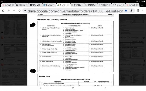
14 - Battery and Charging System
excerpts;
Screenshot_20230105-112356_Chrome.jpg


15 - Audio Systems
17 - Lighting
18 - Electrical Distribution
Each Section covers a component or system. The second set of numbers on each page
indicates the section.
If the vehicle has more than one type of component, such as two types of engines or power
steering systems, alphabetical suffixes are used.


Haynes Red Manual for 80-95 Bronco & F Series @ Hanes guide 80-96 bko f series.pdf via BroncMom!

See my mostly recovered View attachment 202203
site by schwim @ Ford Bronco And F-150 Links - FORD BRONCO
Al
 

Attachments

  • Screenshot_20230105-112336_Chrome.jpg
    Screenshot_20230105-112336_Chrome.jpg
    287.9 KB · Views: 5
  • Screenshot_20230105-112351_Chrome.jpg
    Screenshot_20230105-112351_Chrome.jpg
    231 KB · Views: 5
OP
OP
zalkins

zalkins

New member
Joined
Feb 3, 2022
Messages
4
Reaction score
0
Location
Oregon
So an update for ya fellas. Sorry for the delay. The short went deep into the fuel pump. I ended up cutting a panel and replacing the pump, and a few butt connectors. Nothing...... so I hotwired a switch for the moment.

Soo. few issues happened. The pump... I pulled the old float from the old pump and a yellowish wire to the board inside the sender module broke off right on the Solder contact. Pump works great but I can't find Just the sender module that attaches to pump anywhere. Just the whole pump again.
Issues:
1)so now my fuel gage is toast. And stays on the right. ^^
2) my amber indicator lights under the headlights will not turn off. I have to disconnect the negative terminal to turn off exterior lights under thet headlights.
3) instrument panel light went out. (Ac/speedom/gas/rpm etc....) stereo and glove box are good.

Thoughts?
.
 

miesk5

96 Bronco 5.0
Staff member
Moderator
Joined
Oct 18, 2005
Messages
9,071
Reaction score
1,019
Location
Floating in the Pacific
Yo Zalkins,
Repair; "...As much of an improvement as the FDM system was over the previous EFI pump system, it's still subject to failures, mostly related to fuel varnish building up on its internal surfaces. When it builds up in the level sender, it causes the gauge to peg FULL, as any open circuit would (high resistance). If diagnosis shows the fault to be inside the tank, the sender can sometimes be cleaned & returned to service for a fraction of the cost of a new sender. In either case, a new O-ring is required between the pump mounting plate & the tank. Instructions for removing the FDM can be found in this album's captions..." READ MORE by Clicking Next
Source: by Steve83

ection 17-01: Lighting, Exterior
1996 F-150, F-250, F-350, F-Super Duty Motorhome and Bronco Workshop Manual​
DIAGNOSIS AND TESTING

Inspection and Verification, Parking Lamps​

  1. Verify the vehicle owner's original concern by operating the parking lamps to duplicate the original condition.
  1. Inspect to determine if one of the following electrical concerns apply:

    VISUAL INSPECTION CHART
    Electrical​
    • Circuitry open/shorted.
    • Damaged connector.
    • Miniature bulb burned out.
    • Damaged headlamp switch.
  1. If the concern(s) remains after the inspection, determine the symptom(s) and proceed to the following symptom chart.

●PINPOINT TEST T: PARKING LAMPS ON CONTINUOUSLY
T1 CHECK HEADLAMP SWITCH HARNESS
  • Disconnect battery ground cable.
  • Remove headlamp switch harness from the headlamp switch.
  • Reattach the battery ground cable.


o
REPAIR short to power. RESTORE vehicle. RETEST system.GO to T2.
T2 HEADLAMP SWITCH TEST
  • Disconnect the battery ground cable.
  • Reconnect the headlamp switch harness to the headlamp switch. Headlamp switch in OFF position.
  • Reattach the battery ground cable.
Do the parking lights go on?
YES! REPAIR short to power. RESTORE vehicle. RETEST system.
NO. GO TO T2
YesNo
REPAIR short to power. RESTORE vehicle. RETEST system


PINPOINT TEST T: PARKING LAMPS ON CONTINUOUSLY T1 CHECK HEADLAMP SWITCH HARNESS
Disconnect battery ground cable.Remove headlamp switch harness from the headlamp switch.Reattach the battery ground cable.
Do the parking lights go on?

Yes
PAIR short to power. RESTORE vehicle. RETEST system.GO to T2. T2 HEADLAMP SWITCH TEST Disconnect the battery ground cable.Reconnect the headlamp switch harness to the headlamp switch. Headlamp switch in OFF position.Reattach the battery ground cable.

Do the parking lights go on?
Yes. REPLACE miniature bulb. RESTORE vehicle. RETEST system.
No System OK.

YesNo
REPLACE miniature bulb. RESTORE vehicle. RETEST system.

System OK.
 

Attachments

  • Screenshot_20230121-095633_Chrome.jpg
    Screenshot_20230121-095633_Chrome.jpg
    219 KB · Views: 0

miesk5

96 Bronco 5.0
Staff member
Moderator
Joined
Oct 18, 2005
Messages
9,071
Reaction score
1,019
Location
Floating in the Pacific
Yo Z,
Section 13-01: Instrument Cluster, Conventional
1996 F-150, F-250, F-350, Bronco, F-Super Duty Motorhome Chassis Workshop Manual​
REMOVAL AND INSTALLATION

Indicator/Warning Bulbs​

NOTE: The removal and installation procedures are identical for all indicator/warning lamps.
Removal

  1. Disconnect the battery ground cable (14301).
  1. Remove instrument cluster opening finish panels. Refer to Section 01-12.
  1. Remove screws attaching instrument cluster (10849) to instrument panel (04320).
  1. Pull instrument cluster rearward to provide access to the back of instrument cluster.
  1. Turn the desired indicator/warning lamp counterclockwise.
  1. Remove bulb from its socket.

Installation
  1. Follow removal procedures in reverse order.
  1. When installing the instrument cluster bulb, make sure pins are properly seated into the instrument cluster backplate.
  1. Check system operation.

    1674319624164.png

    Rear View of Instrument Cluster (Base), F-Series and Bronco
    1674319684607.png

    Rear View of Instrument Cluster (Optional), F-Series and Bronco Super Duty
1674319716927.png


My Tablet is slow now... will try later,
For now:
Section 13-01: Instrument Cluster, Conventional
1996 F-150, F-250, F-350, Bronco, F-Super Duty Motorhome Chassis Workshop Manual​
DESCRIPTION AND OPERATION

Instrument Cluster​

The cluster warning lamps are located in two vertical columns, one on each side of the instrument cluster (10849) and also along the bottom of the instrument cluster. F-Series and Bronco optional instrument clusters have the warning lights along the right-hand side and bottom of the instrument cluster.

Base Cluster, F-150, F-250, F-350, F-Super Duty and Bronco


k17271e.gif

ItemPart NumberDescription
1Fasten Seat Belt Indicator (Part of 10849)
2High Beam Indicator (Part of 10849)
3Charging System Indicator (Part of 10849)
4Turn Signal Indicator (Part of 10849) (RH)
54x4 High Range (Part of 10849)
6Low Range Indicator (Part of 10849)
7Air Bag Indicator (Part of 10849)
8Not Used
9Turn Signal Indicator (Part of 10849) (LH)
10Brake Indicator (Part of 10849)
11ABS Indicator (Part of 10849)
12Check Engine Indicator (Part of 10849)


Optional Cluster, F-150, F-250, F-350, F-Series, F-Super Duty, F-Super Duty Motorhome and Bronco


k17273e.gif


ItemPart NumberDescription
1Fasten Seat Belt Indicator (Part of 10849)
2Check Engine Indicator (Part of 10849)
3ABS Indicator (Part of 10849)
4Brake Indicator (Part of 10849)
5Turn Signal Indicator (Part of 10849) (RH)
64x4 High Range (4-Wheel Drive Only)
7Low Range (4-Wheel Drive Only)
8Charging System Indicator (Part of 10849)
9High Beam Indicator (Part of 10849)
10Air Bag
11Not Used
12Turn Signal Indicator (Part of 10849) (LH)


Instrument Cluster Display Proveout

When the key is turned to RUN, the following warning lamps will prove out by momentarily lighting.

  • safety belt
  • charging system
  • air bag
  • brake system
  • anti-lock brake
  • check engine lamp
Printed Circuit

The instrument cluster printed circuit (10K843), which supplies current to the instrument panel indicators, gauges, and some clocks, is made of copper foil that is bonded to a polyester base film (usually referred to as Mylar®).

The instrument cluster printed circuit is mounted to the cluster housing and, due to its location, cannot be easily inspected or tested in the vehicle. This makes the instrument cluster printed circuit vulnerable to damage when a probe is used for in-vehicle testing as the probe can pierce the instrument cluster printed circuit or, in some cases, burn the copper conductor.

Since there is no approved procedure for in-vehicle testing of the instrument cluster printed circuit, it must be removed for visual inspection. If no visual damage is evident, each circuit should be tested with an ohmmeter. If an open circuit or short is detected, the instrument cluster printed circuit must be replaced.


Members online

No members online now.

Forum statistics

Threads
22,520
Messages
135,968
Members
25,122
Latest member
Rickyb571
Top