yo SHANE,
WELCOME!
First off, I know when you see my reply, it will look overwhelming, so look at the
highlighted parts first.
Check Fuses 8 & 18 in Cab fuse block (lower left of dash by driver's left knee)
Fuse & Power Distribution Box
Diagram in a 94 Bronco

Source: by Ford via Steve
If no 12 v on Supply Side of each; look in Power Distribution Box (Located under the hood on the drivers side fender liner, on driver's side of the air cleaner housing)
and
check **** FUSE J for Fuses 15 and 18 (IP Fuse Panel), Starter Relay
& S for Fuses 4, 8 and 16 (IP Fuse Panel). Also See Circuit Breaker 12
This problem could be caused by a # of things;
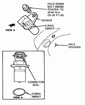
bad vehicle speed sensor (VSS) (also called ABS,, DSS sensor) sensor on top of 8.8 (rear differential)/ or
Connector/corroded wires inside connector; C
heck this first
or cruddy/damaged tone ring in the 8.8. L

VSS location pic in an 8.8 (rear differential) by Shadofax (TheJuice, The Juice, Mark Z)
bad wiring/shorts /connectors from VSS at firewall, at 4WABS Module and /or at PSOM and then onto the PCM the locations of the connectors along the path from VSS to 4WABS and up to Instr Cluster & PSOM are;
C404 VSS On rear axle sensor (A7) Terminals: 02
C205 LH rear of engine compartment, in safety wall (Fire Wall) Terminals: 24 In-Line
C202F & M LH rear of engine compartment, in safety wall (A8) Terminal: 7 In-Line
C119 LH front corner of engine compartment on 4WABS control module (E10),Terminals: 40
O/LB to:
C202F & M LH rear of engine compartment, in safety wall (A8) Terminal: 7 In-Line
C252 Programmable Speedometer/Odometer Module (PSOM), Behind top LH side of I/P, on PSOM (A7) Terminal: 12 Color: B at Pins 4
LG/Y to Splice S107 Engine control sensor harness, from C119 near T/O to G101 (G101 RH side of Radiator support); to PSOM Pin 5
C202 F and M
and spliced to Ground G100 (BK)
G100 & G104 (tied together in diagram) G100 @ LH front of engine compartment, on upper radiator support
G100 Serves Component:
Fuel Pump Module
Inertia Fuel Shutoff
Misfire Sensor
Misfire Sensor Shield
Output Shaft Speed (OSS) Sensor
Powertrain Control Module (PCM), 5.0L
From PSOM Pin 7 (GY/BK) to Splice S246 Main harness, near T/O to speed control amplifier to
C185 PK/O @ PCM 5.0L Powertrain Control Module (PCM) LH side of safety wall, on powertrain control module (PCM) (C10) Terminal: 104 Color: GY
C185, 5.8L Powertrain Control Module (PCM) LH side of safety wall, on powertrain control module (PCM) (C10) Terminal: 104 Color: GY
C185 @PCM to C202 F and M
Splice 216 to Ground G200, Instrument Cluster ground is inside passenger side kick panel
and on to C185 @ PCM PIN 58 (GY/BK) and from Pin 46 to MLPS (TR) Pin 2
Verify PCM & MLPS wiring & Pin numbers using following WIRING DIAGRAMs by Ford via Steve
http://www.supermoto...y/media/95931_1
To bypass the 4WABS module @ it's harness's connector & feed the ABS signal directly to the PSOM,
Disconnect module (under coolant recovery /ws washer tank) & in connector, jumper LG/Bk to LG/Y, and R/Pk to O/LB. Here's a pic of the connector and jumpers; @ 4WABS Module Connector in 93-96; "...jumper 14 (CKT 530, LG/Y) to 21 (CKT 519 (LG/BK) & 39 (CKT 491 (O/LB) to 22 (CKT 523, R/PK)...";
http://img.photobucket.com/albums/v2...rw-jumpers.jpg
Source: by Turbo Ghost
Speed Input Signal Test @ PSOM in 93-96 Bronco; "...NOTE: Only wiring harness end of connector is to be probed. * Connect Rotunda Digital Volt-Ohmmeter 014-00407 or equivalent to Pin 4 (speed in ) and Pin 5 (speed in -). * Does the voltage increase smoothly and continuously from 0 to approximately 3.5 volts as vehicle speed increases from 0 to 48 km/h (0 to 30 mph)? OR: If available, a frequency counter may be connected to Pin 4 (Speed in ) and Pin 5 (Speed in -). Does the displayed frequency of the signal increase smoothly and continuously from 0 to approximately 667 Hz at approximately 48 km/h (30 mph)? OR: * If neither a voltmeter nor frequency counter is available,
cruise control may be used as a good indicator. If it works normally, then the speedometer module is at least receiving a speed input signal and the wiring and sensor & tone
If you have cruise control ws the recall and updates done? Checkk w/local Ford dealer
Defective VSS; "... Anyway, the autozone VSS looks almost identical to the ford VSS. They are both now made of plastic. You have to look very closely to see minor differences. However, the magnet inside does not budge in the ford part, no rattling noise at all. The Autozone part rattles when shaken, ie. the magnet has room to move inside the plastic housing.[/b]It's was a big lesson for me.
Wrong readings from the VSS can cause so much E4OD problems...erratic shifting, late shifting, hard shifting, feeling like it was in neutral, as well as engine cutting off at stop lights---Even if it registers correct readings on your speedometer..."
Source: by bkne40d
Tone Ring Inspection; "Take off the rear diff cover. Check the Ring Tone gear. It is located on the left hand side of the ring gear. Look to see if any of the teeth have been notched (from debris floating around in the diff.) Usually a spider gear. If the ring tone gear has been notched, it will need to be replaced to fix your speedo reading. Jack it up and rotate the tires to look for the teeth to be notched/broken/bent..."
Source: by Bighibbi
See if the 8.8's vent hose is off the ****** atop the diff; water could have gotten in.


