Possible Computer Issue

Disclaimer: Links on this page pointing to Amazon, eBay and other sites may include affiliate code. If you click them and make a purchase, we may earn a small commission.

1989 Bronco 4x4 XLT

New member
Joined
Jul 1, 2011
Messages
22
Reaction score
0
I have 1989 Fullsize with a rebuilt EFI 302 we just put in. We are trying to break it in right now. It starts great when cold but after it warms up and we cut it off it wont restart??? We are getting gas to the injectors and getting a spark at the plugs when it doesn't start. It starts fine when cold and I can restart it multiple times when its cold. For some reason it wont start when its warmed up. I read somewhere else that those are the symptoms for the computer going out? We have replaced a whole lot of stuff in the ignition system already Ign. Switch, Coil, Starter, Starter Solenoid, PIP/Stater in the distributor, ICM, New Wires, Cap, Rotor. Now we replaced some stuff in the fuel system also New Tank, Sending Assembly, and the Filter. I think the computer is not getting the Air/Fuel mixture right for when it is already warmed up. We have the timing set perfect! It runs so good. We just can't get it to fire up when warm. Is there any other ignition components that could be failing? Or could there be something that is getting too hot like being too close to the motor? Could it be a short somewhere. I unwrapped the engine wiring harness during the rebuild and looked for nicked wires that could short and couldn't find anything. I also did install the Ignition Switch correctly. Which is what we thought was the problem(installed wrong). Any help would be appreciated.

Ken


miesk5

96 Bronco 5.0
Staff member
Moderator
Joined
Oct 18, 2005
Messages
9,071
Reaction score
1,020
Location
Floating in the Pacific
yo KEN!

yo,

As long as the Bronco had a 302 EFI in it as built, you're ok so far.

Try a Self Test for Codes by my pal, BroncoJoe19[/urlAn assistant to write the info is helpful


heat the engine up; idle until temp gauge is in normal range you usually see


and when it warms up; shift thru all gears incl Reverse anyway.


Then turn off all accessories/lights, etc.


Make sure A/C is off and transmission is in Park (automatic)


Do Key On Engine Off (KOEO) portion first.


The engine temperature must be at least than 50°F for the KOEO portion & more than 180°F for the KOER portion.


Look Codes up in my broncolinks.com site using the new Search function if in a hurry today.


Search for:


DTC (space) (insert code)


And Post em here according to


KOEO


& KOER


A GUESS is the TFI's Hall Effect (aka Profile Ignition Pick-up (PIP) Signal, Stator, RPM)


Somre resources;


Testing, Overview & Diagrams; "...The Thick Film Integrated (TFI-IV) ignition system uses a camshaft driven distributor with no centrifugal or vacuum advance. The distributor has a diecast base, incorporating a Hall effect stator assembly. The TFI-IV system module is mounted on the distributor base, it has 6 pins and uses an E-Core ignition coil, named after the shape of the laminations making up the core. The TFI-IV module supplies voltage to the Profile Ignition Pick-up (PIP) sensor, which sends the crankshaft position information to the TFI-IV module. The TFI-IV module then sends this information to the EEC-IV module, which determines the spark timing and sends an electronic signal to the TFI-IV ignition module to turn off the coil and produce a spark to fire the spark plug. The operation of the universal distributor is accomplished through the Hall effect stator assembly, causing the ignition coil to be switched off and on by the EEC-IV computer and TFI-IV modules. The vane switch is an encapsulated package consisting of a Hall sensor on one side and a permanent magnet on the other side. A rotary vane cup, made of ferrous metal, is used to trigger the Hall effect switch. When the window of the vane cup is between the magnet and the Hall effect device, a magnetic flux field is completed from the magnet through the Hall effect device back to the magnet. As the vane passes through the opening, the flux lines are shunted through the vane and back to the magnet. A voltage is produced while the vane passes through the opening. When the vane clears the opening, the window causes the signal to go to 0 volts. The signal is then used by the EEC-IV system for crankshaft position sensing and the computation of the desired spark advance based on the engine demand and calibration. The voltage distribution is accomplished through a conventional rotor, cap and ignition wires. GENERAL TESTING - Spark Plug Wire Resistance Whenever the high tension wires are removed from the plugs, coil, or distributor, silicone grease must be applied to the boot before reconnection. Use a clean small screwdriver blade to coat the entire interior surface with Ford silicone grease D7AZ-19A331-A, Dow Corning #111, or General Electric G-627. Use spark plug wire removal pliers, or grasp firmly at the boot (not the wire itself) and remove the wires from the plugs, then remove the distributor cap. Measure the resistance through the distributor cap at that end. Resistance on these wires must not exceed 5,000 ohms per foot. Do not pierce any ignition wire for any reason. Measure only from the two ends. Adjustments - The air gap between the armature and magnetic pick-up coil in the distributor is not adjustable, nor are there any adjustment for the amplifier module. Inoperative components are simply replaced. Any attempt to connect components outside the vehicle may result in component failure. - TROUBLESHOOTING THE TFI-IV SYSTEM; After performing any test which requires piercing a wire with a straight pin, remove the straight pin and seal the holes in the wire with silicone sealer. Wiring Harness - Disconnect the wiring harness connector from the TFI module; the connector tabs must be PUSHED to disengage the connector. Inspect the connector for damage, dirt, and corrosion. Attach the negative lead of a voltmeter to the base of the distributor. Attach the other voltmeter lead to a small straight pin. With the ignition switch in the RUN position, insert the straight pin into the No. 1 terminal of the TFI module connector. Note the voltage reading. With the ignition switch in the RUN position, move the straight pin to the No. 2 connector terminal. Again, note the voltage reading. Move the straight pin to the No. 3 connector terminal, then turn the ignition switch to the START position. Note the voltage reading then turn the ignition OFF . The voltage readings should all be at least 90 percent of the available battery voltage. If the readings are okay, proceed to the Stator Assembly and Module test. If any reading is less than 90 percent of the battery voltage, inspect the wiring, connectors, and/or ignition switch for defects. if the voltage is low only at the No. 1 terminal, proceed to the ignition coil primary voltage test. Stator Assembly and Module - Remove the distributor from the engine. Remove the TFI module from the distributor. Inspect the distributor terminals, ground ****** and stator wiring for damage. Repair as necessary. Measure the resistance of the stator assembly, using an ohmmeter. If the ohmmeter reading is 800-975 ohms, the stator is okay, but the TFI module must be replaced. If the ohmmeter reading is less than 800 ohms or more than 975 ohms; the TFI module is okay, but the stator module must be replaced. Repair as necessary and install the TFI module and the distributor. - Primary Circuit Continuity; This test is performed in the same manner as the previous Wiring Harness test, but only the No. 1 terminal conductor is tested (ignition switch in Run position). If the voltage is less than 90 percent of the available battery voltage, proceed to the coil primary voltage test; rotary armature has open areas called windows and tabs called vanes..." miesk5 NOTE; stator is a Hall Effect device, which uses a magnetic field. It sits under the distributor cap and picks up a signal from a wheel with teeth. (miesk5 NOTE; this wheel is a rotary armature that has open areas called windows and tabs, called vanes). The wheel has the same number of teeth as cylinders in the engine and moves at the same speed as the distributor and camshaft. If you have a V8 then the wheel has eight teeth; seven teeth are the same and one tooth is smaller to identify cylinder #1. As the wheel spins with the distributor is breaks the magnetic field of the hall devise generating a sine wave. This sine wave is called the raw Profile Ignition Pickup (PIP) signal and indicates the engine status at 10deg. BTDC. Now some people think the TFI is responsible for this, but that is incorrect; the PIP signal passes thru the TFI unaltered to the computer.(by Ryan M)


Source: by Chilton via autozone.com


I'll delete your other post; no problemo Ken


Last edited by a moderator:

BroncoJoe19

Active member
Joined
Dec 26, 2007
Messages
2,092
Reaction score
12
Location
New Jersey
Code 21 ECT out of self test range 0.3 to 3.7 volts.

Engine Coolent Temp sensor. that makes sense for your issues.

 
Last edited by a moderator:
OP
OP
1989 Bronco 4x4 XLT

1989 Bronco 4x4 XLT

New member
Joined
Jul 1, 2011
Messages
22
Reaction score
0
But I just now bought a new one ,installed it and the problem is still there.

 
Last edited by a moderator:

BroncoJoe19

Active member
Joined
Dec 26, 2007
Messages
2,092
Reaction score
12
Location
New Jersey
The problem is still there, in that it will not start once hot? OR the codes are still there?

Did you clear your codes after installing the ECT?

 
OP
OP
1989 Bronco 4x4 XLT

1989 Bronco 4x4 XLT

New member
Joined
Jul 1, 2011
Messages
22
Reaction score
0
Sorry but how do you clear the codes. The temperature gauge is reading the engine warm up. When we are watching it, it gets to about the middle and then you could see the thermostat kick in. It goes back down a little. And why does under my profile picture say Wheres my hammer. I didn't put that there????

 
Last edited by a moderator:

nelbur

New member
Joined
Oct 30, 2010
Messages
132
Reaction score
0
The ECT has nothing to do with the temperature gauge. It is what tells the computer how hot the engine is. I know from personal experience that it can keep a hot engine from starting. Are you SURE you have fire when it will not start. Just in case there is confusion about where the ECT (engine coolant temp. sensor)is, it is on a short riser that feeds the heater hose, below the throttle body.


BroncoJoe19

Active member
Joined
Dec 26, 2007
Messages
2,092
Reaction score
12
Location
New Jersey
The EVTM for my 90 bronco lists the base part number for the Engine Coolent Temp Sensor as 12A648, and the engine temp switch as 10884.

As mentioned above, the temp switch is for the temp guage. The ECT is for the EEC to set timing, and fuel trims depending upon the engine temp.

My EVTM lists the ECT location as Front of engine, on the thermostat housing and the location of the temp switch on the front LH (driver's side) of the engine.


miesk5

96 Bronco 5.0
Staff member
Moderator
Joined
Oct 18, 2005
Messages
9,071
Reaction score
1,020
Location
Floating in the Pacific
yo,

http://i165.photobucket.com/albums/u64/Rwanda01/Bronco/ECTs001copy.jpg

ECT Location pic in an 89 351W; behind/& passenger side of the distributor Source: by BigBlue89Bronco

Location Diagram in 87-91 (from Factory Manual and the Ford Electrical & Vacuum Troubleshooting Manual (EVTM) Source: by Broncobill78 (Dave) at Ford Bronco Zone Forums

Ford went from two-digit to three-digit EEC IV Self-Test codes in 1991

DTC 21 ECT out of self test range 0.3 to 3.7 volts;

"... engine not warmed up, bad thermostat, low coolant..

Coolant is less than 50 deg F for KOEO, or less than 180 deg F for KOER, or greater than 250 deg F for either. I would check the thermostat too.

If coolant temp is in proper range, suspect ECT sensor or it's connector/wiring.

Testing; "..."But due to its simplicity of design, the ECT is rarely at fault when problems occur. Before testing the ECT or any other EFI component perform a self-test, trouble codes received during test can be used as a diagnostic tool along with other indicators. To test an ECT sensor you will need a volt meter. You can test the ECT by back probing the harness while reading the voltage returning to the EEC. Or you can removing the connector completely and test the resistance between the 2 pins on the ECT..." READ MORE Source: by Ryan M (Fireguy50) at fordfuelinjection.com

"Before you start blaming the engine coolant temperature sensor and replacing it make sure the rest of the coolant system is in good condition. All of the following items will affect the ECT:

*Coolant level

*Radiator Fan

*Water Pump

*Water Pump and Fan Belts

*Thermostat

*Base Timing

*Engines general condition

*Harness and wire general condition

See site for diagrams and test chart & connector pin-out info

The Engine Coolant Temperature (ECT) sensor is a thermal transistor, which means it allows less electricity to pass through the sensor the warmer it gets. The ECT receives the �Signal Return� voltage from the EEC, then allows a certain amount to return back to the EEC. Because the ECT is in direct contact with the engine coolant flow it changes resistance in response to the temperature of that coolant.

The ECT is third in command in the hierarchy of EFI sensors, this means this sensor is very important when calculating fuel ratios and timing curves. This is because of simply chemistry; fuel and spark are constants in the equation. Air is the biggest variable in combustion; it changes density greatly over a range of temperature. So keeping track of the changing temperatures of the incoming air and the engine in which it is burnt becomes very important. But due to its simplicity of design, the ECT is rarely at fault when problems occur.

Before testing the ECT or any other EFI component perform a self-test, trouble codes received during test can be used as a diagnostic tool along with other indicators. To test an ECT sensor you will need a volt meter. You can test the ECT by back probing the harness while reading the voltage returning to the EEC. Or you can removing the connector completely and test the resistance between the 2 pins on the ECT. The engine temperature must be greater than 50�F (10�C) to pass the KOEO Self-Test and greater than 180�F (82�C) to pass the KOER Self-Test. To accomplish this, the engine should be at normal operating temperature.

Values were calculated for VREF = 5.0 volts. These values may vary 15 percent due to sensor and VREF variations."

MIESK5 NOTE; if VREF is Not 5.0 volts or close. then there is a wiring/connector terminal issue from EEC to ECT or possibly EEC damage. But other Sesnors' (such as TPS, EGR, etc.) codes would come up if EEC is damaged or VREF is off. VREF wires share the same reference voltage circuit w/ many sensors & share the same ground circuit.

miesk5 NOTE; batty should be 12.6 volts at rest after a charge

DTC 21, 51, 61 or 116, 117, 118 "...Failure in either the circuit or temperature sensor will show code 21, 51, 61 or 116, 117, 118.Unplug the harness connector. First, check the signal voltage at the connector with the key on, engine off. Should be approximately 5.0v. Then, check the resistance of the sensor cold. Should be between 58,750 to 40,500 ohms. Plug in the harness connector and warm up the engine to normal operating temperature. Then, unplug and check the resistance of the sensor hot. Should be 3,600 to 1,840 ohms...'

Source: by Seattle FSB

Wiring Diagram in 87-89 Bronco & F series (Mitchell)

1236.jpg

Source: by equivalent (Beetlejuice) at SuperMotors.net

===--------------

DTC 12 can't control engine RPM high RPM self test; vacuum leak, TB base idle off, IAC dirty or bad, EGR stuck open. Check the IAC valve port in TB for Sludge; Suspect throttle body coking.

Source: by miesk5

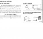
Idle Air Control (IAC); also called, Idle Air Bypass (IAB), Idle Speed Control (ISC), Throttle Bypass Air, Idle Bypass, Inlet Air Controller, Inlet Air Bypass, Intake Air Bypass, Intake Air Control

Idle Air Control (IAC) Sludge; Poor Idle TSB 91-25-07 for 85-92 Bronco & F Series & many others; "...Hard cold starts, hesitation and stalls on initial start-up or during idle or decel may be caused by sludge in the throttle body and/or idle by-pass valve. Sludge deposits or oil film on the throttle body bore and plate or the idle air by-pass valve may cause one or more of the following conditions. Hard Cold Start, Stall On Initial Start-Up, Stall During Idle, Stall During Decel, Rough Idle, Rolling Idle, Hesitation During Acceleration. A new idle air by-pass service kit (F2PZ-9F939-A) is now available for service use to correct sludge contamination concerns of the throttle bore and plate only. It eliminates the need to clean the majority of past model throttle body applications. Cleaning is not required on sludge tolerant throttle body designs released for 1991 and newer model years..." Source: by Ford via Steve83

There is another person working w/this TSB here in another thread; he is about to modift the IAC Gasket to allow more air flow in instead of buying the new part.

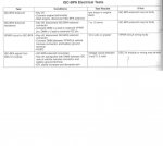
Testing & Diagnostic Trouble Codes (DTC), Chapter 12, from Ford Fuel Injection and Electronic Engine Control: How to Understand, Service and Modify, 1988-1993

Source: by Charles O. Probst @ http://www.yunost.ru/docs/Ford-injectors-book/Part12/Part12-1/Part12-1.pdf

7.66 MB pdf file

See page 292; ISC-BPS

 
Last edited by a moderator:

miesk5

96 Bronco 5.0
Staff member
Moderator
Joined
Oct 18, 2005
Messages
9,071
Reaction score
1,020
Location
Floating in the Pacific
yo KEN

Nelbur is the person here that is modding the IAC Gasket

@ http://broncozone.com/topic/22150-fast-idle-problem/

here it is; "I checked on the Idle Air Service Kit that Miesk5 mentioned. Ford has them for $89, and an outfit named TOMCO has "one" for $64. It is just a spacer with set screws that allow air to bypass the IAC. I'm too cheap to pay that kind of money to solve my stall on hot start problem. I've grown used to catching it with a bit of accelerator when it starts up. I think I will try cutting away some of the gasket between the air holes, to allow air to bypass the IAC. It could be adjusted by trial and error by cutting away more gasket, and the gasket could even be doubled up if more bypass is needed. Anyone know why this cheapskate fix would not work?"

my reply was;

yo,

concept could work;

"...That is an adjustable idle plate....aka....idle air metering block...aka idle-fixer. You can get it from your Ford dealer. Last one I bought for a customer's truck was about $85 and it came with new mounting screws. made my own (fixed-orfice) plate by cutting a piece of 1/8" flat bar to the shape of my IAC Valve gasket and drilling the passage holes 3/32". I started with 1/16" holes but that weren't quite large enough for my particular engine. Point there is that different engines may require their own orfice size....hence the two adjustments on the Ford (factory) version. These things have been in use for 15 years that I know of, maybe more.....which tells me that Ford has known all along that they had a design glitch in their EFI idle air valve system..."

Source: by DGW1949

IAC Overview & test by probst

IACovervirewbyprobst.JPG

IACtestbyprobst.JPG


nelbur

New member
Joined
Oct 30, 2010
Messages
132
Reaction score
0
The sensor you listed is the sending unit for the gauge, and has nothing to do with how the engine runs. The ECT tells the computer how hot the engine is and can be located on your 302 by following the heater hose into the top of the engine just behind the thermostat housing. Replacing the ECT fixed my problem this summer where my Bronco would not start hot, but would start if it cooled a bit. I had the same ETC code that you have.

 
Last edited by a moderator:
OP
OP
1989 Bronco 4x4 XLT

1989 Bronco 4x4 XLT

New member
Joined
Jul 1, 2011
Messages
22
Reaction score
0
PROBLEM SOLVED!!!!! Well at least the big one. I replaced the other temp sensor and now it starts when hot. We cleared all the codes before we drove it to star new when we took it out. Well it has sat in the previous owners driveway for two years and then ours for about a year. Anyway the transmission when going through the gears was really rough slipping pretty bad at first but the more we drove it the more smoother it got. Now it pretty smooth you almost cant really feel it shift. I guess it just needed to get loosened up. Now its allot smoother. By the way I dropped the tranny pan and replace the filter and fluid. The motor is idling at 1500 rpm. Sounds high only when in park. When we put it in drive the idle goes way down. Cant remember where though on the gauge. I saw when it was cold the rpm gauge would fluctuate 1000 and 1500. Was that the choke warming it up? If it was then the new sensor must be giving the coputer the right info. While we were driving the orange check engine light came on and then shortly went off. Then later on, a red check engine light came on and then shortly went off. So when we got back we pulled the KOEO codes. This is what I got 11,14,13,22,34,3. I also got an exhaust leak on the passenger side. I think we need to tighten the exhaust to header bolts up. Thank you soooooo much Miesk5,BroncoJoe19,Nelbur, and Bronco Kid! for all the help.

Ken


BroncoJoe19

Active member
Joined
Dec 26, 2007
Messages
2,092
Reaction score
12
Location
New Jersey
I'd clear my codes and see if they re-occur.

Since the ECT participates in setting fuel trims, I'd clear codes by pulling the neg bat cable for a few minutes.


BroncoJoe19

Active member
Joined
Dec 26, 2007
Messages
2,092
Reaction score
12
Location
New Jersey
I didn't check to see what the codes meant, but an exhaust leak before the O2 sensor can cause the engine to run rich because the O2 sensor may read too much O2 in the exhaust. This may be the cause of the high surging idle.

So YES.. you should tighten and eliminate any exhaust leak.

 
OP
OP
1989 Bronco 4x4 XLT

1989 Bronco 4x4 XLT

New member
Joined
Jul 1, 2011
Messages
22
Reaction score
0
Ok I pulled off the negative battery cable for a few minutes. I then started it and let it run till it got to normal operating temp. Shut it off and pulled the KOEO codes. I got 11,11,1,11,11. The manual that came with the code reader says that code 11 means system pass. Why is it repeatedly telling me 11. I pulled the codes twice and got the same thing.


Members online

No members online now.

Forum statistics

Threads
22,522
Messages
136,005
Members
25,129
Latest member
Boone_23
Top