Temp Gauge testing

Disclaimer: Links on this page pointing to Amazon, eBay and other sites may include affiliate code. If you click them and make a purchase, we may earn a small commission.

AQNW

New member
Joined
Jun 4, 2007
Messages
5
Reaction score
0
Hi, Fellas - Thanks for a great forum. I've been trying to run down a prob with my 1996 Bronco XLT 5.8L, and hoped some of the experts could help. I get no reading on the temperature gauge cold or hot, and I replaced the temp sensor recently. I tore into it again this past weekend and came up with a few questions I hoped folks could answer.

Yes, I installed the sensor with thread tape, so I'm gonna remove that soon. But, what's funny is I am seeing a resistance drop across the temp gauges SIG & GND leads on the plug to the back of the instrument cluster. Cold (about 95deg ambient) I measured 35ohms and that dropped to about 28ohms the engine warmed up. Those numbers may not be right, but my temp sensor seems to be doing something. When I swapped the sensor I put them both in hot water and measured a resistance change as they warmed, so I'm pretty sure my old sensor wasn't bad.

However, I read a post here (or on another forum) that said there might be another temp sensor, and that the one on the front of the intake could be for the Powertrain Control Module (PCM) exclusively. That led me to the 96 Bonco wiring diagrams in the Vehicle Repair Info online manuals at www.autozone.com (specifically http://www.autozone.com/images/cds/gif/lar...3d800a3a59.gif), and I did see a two wire sensor config (gry/red, lt grn/red) feeding pin-38 on the PCM. What I didn't see on this diagram or the others are a 2nd sensor, and the actual wiring/electrial source feeding the plug to the back of the instrument panel (wires not the same color as at the sensor).

Does anyone know or have a diagram that describes the electrical path from the PCM to the cluster? Has anyone measured the voltage/resistance at the plug feeding the temp gauge? Are my numbers just way off? I pulled the temp gauge from the cluster to measure resistance across it, and did see some ohms (can't remember how many), not an open (infinite resistance) like I would expect with a burned out/damaged gauge. Does anyone have numbers for normal resistance across the gauge?

I searched the forum for other temp gauge problems, but didn't see the detail I'm asking for. I really suspect a broken gauge, but so far the sensor seems good, the wiring seems good, even the gauge seems good. I'd really appreciate any help/advice you might have. Thanks!

Eric

 
Last edited by a moderator:

Seabronc

New member
Joined
May 22, 2004
Messages
7,315
Reaction score
35
Location
North of NYC
The temperature sensor that feeds the gauge has a single wire on it. The wire is red with a white stripe. the sender is just to the right and slightly aft of the distributor. Not sure about the resistance readings, but it does sound like it is functioning. Could be the meter itself, but the sender is cheap and though I don't normally recommending shot gunning a problem, but this is a cheap part. If you determine that it is the meter, try to get one out of a junker, new ones are expensive.

Good luck,

:)>-

The gauge depends on good grounding. Check the grounding of the instrument panel. There should be a ground connection from the rear of the engine to the fire wall also. Remove the leads, clean the connections and reconnect.

 
Last edited by a moderator:

Seabronc

New member
Joined
May 22, 2004
Messages
7,315
Reaction score
35
Location
North of NYC
P.S. Welcome to the Zone > . Put a post in the Introductions forum and post some pictures of your truck, we'd like to :-B them.

:)>-


BLADE262US

Active member
Joined
Feb 21, 2004
Messages
1,713
Reaction score
5
Location
Michigan
If you take that single wire that Seabronc is talking about and ground it to the block the guage will imediately go to HOT that will tell you if its the guage or the sender . There is another mounted back farther in the intake and that is for the EEC to determine timing curves and injector pulse time . :D /emoticons/[email protected] 2x" width="20" height="20" />

 
OP
OP
A

AQNW

New member
Joined
Jun 4, 2007
Messages
5
Reaction score
0
Thanks Sea & Blade - I finally found the one wire hookup and did some testing. (Pretty clear I changed the wrong sensor, doh!) The red/wht wire seems ok when I created a loop, no short that I found. But when I touched it to GND, unfortunately the gauge didn't move. Probably bad gauge, right?

I was curious whether there was any other way to confirm whether the gauge itself is good or bad. If it were burned out, I would expect an open (infinite resistance) across SIG to GND, but I'm seeing some 36ohms and about double that from IGNition to GND.

Every once in a while the gauge will move about 1/4 toward hot when I turn the key on, so there appears to be some continuity there, but it almost immediately returns to full cold. I'm assuming the gauge is measuring a differential of Volts or Amps between the 12V hot (IGN) and that seen on the SIG wire thru the sensor. Is this correct? I'm also assuming that if I supplied 12V to the SIG lead on back of gauge, then grounded the GND lead, the gauge should jump to full hot (as Blade said). Is this correct?

Before buying used/new gauge, just trying to devise any test to prove the gauge is broken. Any other ideas? Again, thanks for your help.

Eric

 
Last edited by a moderator:

BLADE262US

Active member
Joined
Feb 21, 2004
Messages
1,713
Reaction score
5
Location
Michigan
Man Im not sure what color the other end is that feeds power to the guage but your controlling the ground through a variable resistor ( the sensor ) . It kinda sounds like it may not have a good connection to the power source if you pull the guage you can see the traces and follow the one to the guage and check to see if theres power there maybe try grounding the sensor wire again and gte in and wiggle the key if you see a reaction then maybe the ignition switch is going bad Ive always known the guages to be a working or not working type of thing not intermitten . If you can find the wire let meknow and Ill look it up theres no easy way to check the guage pack plug from under the dash so you must pull the guage pack out not a big deal just take your time . :D /emoticons/[email protected] 2x" width="20" height="20" />


Seabronc

New member
Joined
May 22, 2004
Messages
7,315
Reaction score
35
Location
North of NYC
OK found the sender resistance values, 74 ohms Cold and 9.7 ohms hot. I wouldn't mess around with putting voltage on the red with white stripe wire. Voltage is supplied to the instruments from fuse 17, (10 Amp), which is hot in START and RUN. That fuse also feeds the Fuel gauge, voltmeter, and Oil pressure gauge. The red with white stripe wire connects through a center tap on the meter which is an internal connection you can't get to. The wire is the same color at both ends and goes through two connectors to get to the sender. Check the continuity from one end to the other, one of the connectors is the through the fire wall connector, (just under and to the right of the brake booster as looking at it from the front of the truck), and the other is C101 which is on the driver wheel well in front of the engine compartment fuse box. Both are possible problem areas as they tend to get corrosion on the contacts after a number of years.

Good luck,

:)>-

 
OP
OP
A

AQNW

New member
Joined
Jun 4, 2007
Messages
5
Reaction score
0
Thanks again, Sea & Blade - I've done a little more testing and found that I can measure some resistance at the temp sensor (about 550 ohms cold, dropping to 420 or so as it warms), so I know it's not fused closed (zero resistance) or burned out open (infinite resistance), and that it's got a good ground. Sea, i think you said the sensor should measure 74 ohms cold, like 29 ohms hot. Is there an online reference you could point me to, as most other articles I've read have been much higher resistance for cold reading.

I also measured some 5V on the red/wht wire at the sensor when I had expected to see 12V. I found a good article re: Ford instrument gauges (though not necessarily the 96 Bronco series) at this link: http://www.mustangandfords.com/techarticle...nt_electricity. They say there is a voltage regulator that steps voltage from 12V to 5V for the gauges, can you confirm this is true for my Bronco? If so, then 5V at the temp sensor seems right.

I'm not sure what else to check here. Since the oil pressure gauge has power, I know the temp gauge has power 'cause it's on the same circuit board trace. There's no short on the red/wht wire, and 5V power to the sensor which has a good ground. I may stop @ auto parts outlet and measure resistance on new sensor just to be sure my numbers aren't way off.

I welcome any/all suggestions here before I buy a new gauge. Thanks again for your help.

 
Last edited by a moderator:

Seabronc

New member
Joined
May 22, 2004
Messages
7,315
Reaction score
35
Location
North of NYC
Thanks again, Sea & Blade - I've done a little more testing and found that I can measure some resistance at the temp sensor (about 550 ohms cold, dropping to 420 or so as it warms), so I know it's not fused closed (zero resistance) or burned out open (infinite resistance), and that it's got a good ground. Sea, i think you said the sensor should measure 74 ohms cold, like 29 ohms hot. Is there an online reference you could point me to, as most other articles I've read have been much higher resistance for cold reading.
I also measured some 5V on the red/wht wire at the sensor when I had expected to see 12V. I found a good article re: Ford instrument gauges (though not necessarily the 96 Bronco series) at this link: http://www.mustangandfords.com/techarticle...nt_electricity. They say there is a voltage regulator that steps voltage from 12V to 5V for the gauges, can you confirm this is true for my Bronco? If so, then 5V at the temp sensor seems right.

I'm not sure what else to check here. Since the oil pressure gauge has power, I know the temp gauge has power 'cause it's on the same circuit board trace. There's no short on the red/wht wire, and 5V power to the sensor which has a good ground. I may stop @ auto parts outlet and measure resistance on new sensor just to be sure my numbers aren't way off.

I welcome any/all suggestions here before I buy a new gauge. Thanks again for your help.
The numbers I gave you were from the Ford EVTM, so I assume they know what they are talking about in spite of what some one else said in an article. If you are a really interested in troubleshooting problems yourself, get a copy for your truck. They come up for sale on ebay all the time. It is the single most useful book for troubleshooting you can get. http://cgi.ebay.com/ebaymotors/1995-Ford-B...sspagenameZWD1V

I'd pull it out clean the threads and reinstall it, (with nothing on the threads, they need the contact with the manifold to make the ground connection, also check the grounding of the battery to the engine and from the engine to the firewall. There should be a small ground strap from the back of the manifold to the fire wall.

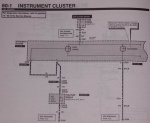
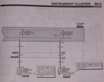
As far as the regulator goes, they use to be on the back of the instrument panel. I do not know if they are still there, that is one of the things that is not shown in the 95 EVTM, but the diagram indicates it is still there. 12V goes to the meter and the center tapped wire goes to the sender,the voltage regulator is attached on the other side of the instrument.

Diagram attached

:)>-

Ford_curtesy_lights_012.jpg

Ford_curtesy_lights_013.jpg

 
Last edited by a moderator:
OP
OP
A

AQNW

New member
Joined
Jun 4, 2007
Messages
5
Reaction score
0
Hi, All - I appreciate all your help here. I did invest in an EVTM manual, but with few other options, I ordered a used cluster from eBay for about $38. It had no tach and miles were some 205k, but this didn't really bother me since all I wanted was the temp gauge out of it.

I plugged in the new used cluster and temp was finally showing some movement proving that all my other stuff was good. I swapped the temp gauges from new to old, put it all back together and it seems to be working good.

The only question I have now is getting my temp indicator needle aligned correctly. Did my best to pull the needles from the same positions (full cold) and not jostle the gauges very much. Not sure how well I did as the indicator at it's highest goes to the middle of the "N" in NORMAL.

Anyone have an idea how I could align the needles? I'm assuming it's got a 195deg thermostat, and the needle should be between "R" and "M". I may get a cooking thermometer and measure radiator temp to see how close I am. Maybe just repositioning the needle would help.

Any other suggestions? Thanks very much. Sincerely,

Eric


Roadkill

New member
Joined
May 29, 2005
Messages
940
Reaction score
7
Location
Killeen, TX
For what it's worth, my guage rarely makes it up to the "o". Going down the road at highway speed, it flucuates between just before the "N" and just before the "o" as the thermostat opens and closes. It's probably a good idea to verify the temp with a thermometer, but I think your probably OK as is.


BroncoAZ

New member
Joined
Jul 1, 2008
Messages
6
Reaction score
2
Thanks for the info on the second sensor. I was working on the folks bronco and this info helped.


Members online

No members online now.

Latest posts

Forum statistics

Threads
22,521
Messages
135,985
Members
25,127
Latest member
JohnK
Top