Trouble Codes: P0401 and P0411

Disclaimer: Links on this page pointing to Amazon, eBay and other sites may include affiliate code. If you click them and make a purchase, we may earn a small commission.

FSB_Rookie

New member
Joined
May 21, 2011
Messages
2
Reaction score
0
Location
Upstate NY
I acquired a 1996 full size bronco 2 years ago with 136k miles. It was in very good condition considering we are in the northeast. Within 3 weeks after I got it I had to replace the EGR valve. Now with 163k miles I have trouble codes P0401 and P0411. I have been driving and resetting, driving and resetting, driving and resetting waiting for the snow to finally melt to tackle this problem. Well today is the day. I read all the available postings I could find on these two trouble codes.


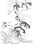
I check all the vacuum lines I could reach. Aside from one that is questionable, but tested as intact, I can't find any vacuum leaks. I tested the EGR valve with vacuum pump and it does not move at any level of vacuum pulled. I have a new one ordered and I will hopefully replace that tomorrow.


My question is: Can the malfunctioning EGR cause or create any conditions that would trigger the P0411 Secondary Air injection incorrect? Do I have two separate problems?


I need to get this fixed soon as my inspection has expired and it will not pass the emissions inspection. The Highway Patrol does not have the same libertarian view of emissions inspections that I do and I can only drive the back roads for so long!


Thanks for your assistance.


miesk5

96 Bronco 5.0
Staff member
Moderator
Joined
Oct 18, 2005
Messages
9,071
Reaction score
1,018
Location
Floating in the Pacific
yo,

Welcome to the Zone!

 P0401 EGR Flow Insufficient Detected Possible Causes; "...DTC P0401 is for exhaust gas recirculation (EGR) insufficient flow detected. This most likely means one or more of the following has happened: The EGR valve may not be opening due to a lack of vacuum; There is a blockage in the EGR (most likely carbon buildup); The DPFE sensor is faulty and needs to be replaced; The EGR valve is faulty. In fixing this code, it is quite common for people to just replace the EGR valve only to have the OBD code return. However, just like many other DTCs, the problem is not always obvious and the EGR valve is not always the culprit..." READ MUCH MORE Source: by Gateway Clean Air Program dnr.mo.gov

DPFE Sensor Overview, Construction, Testing & Depiction, Older Aluminum Version; "...DPFE SIG is This voltage at idle is approximately 0.45 volts; SIG RET is GROUND; V REF is 5 volt reference. DTC PO1400, P1401, PO402, P1403, P1408; "There are a number of tests that the EGR system is put through. First the DPFE is checked. It is continuously monitored for opens or shorts. The OBD II system looks for the DPFE signal to exceed the minimum or maximum values. If it finds these values out of specs a DTC P01400 or 1401 will be set The OBD II system also monitors the EGR flow rate. At a steady state condition when the engine load and speed are moderate and the EVR duty cycle is high the DPFE voltage is checked. It then compares this DPFE value to a stored desired DPFE value for those conditions. If the two values are inconsistent, the EGR flow is insufficient (Fig. 11). A DTC P0401 will be set for this condition. This test is also performed during a Key On Engine Running (KOER) test. If it fails during this test a DTC 1408 will be set; The OBDII system monitors continuosuly the DPFE signal at idle. Since there should be no EGR flow at idle, the DPFE signal should show a no flow voltage signal. The system compares the Key On Engine Off (KOEO) stored voltage to the DPFE signal at idle. If the signal is not consistent with this value, it may indicate a stuck open EGR valve. The DTC for this condition is a P0402. The EVR is continuously tested for opens or shorts. The OBDII system looks for a circuit voltage that is out of range or inconsistent with the EVR commanded output state. If it finds a fault in the EVR circuit voltage a DTC P1409 will be set. There are a number of tests that the EGR system is put through. First the DPFE is checked. It is continuously monitored for opens or shorts. The OBD II system looks for the DPFE signal to exceed the minimum or maximum values. If it finds these values out of specs a DTC P01400 or 1401 will be set. The system then looks for a DPFE voltage value that is inconsistent with a no flow situation. If the DPFE voltage increases or decreases this may indicate a fault with the upstream hose. A DTC P1405 will be set for this condition. A DTC P1406 will be set if there is a problem with the downstream hose. The OBD II system also monitors the EGR flow rate. At a steady state condition when the engine load and speed are moderate and the EVR duty cycle is high the DPFE voltage is checked. It then compares this DPFE value to a stored desired DPFE value for those conditions. If the two values are inconsistent, the EGR flow is insufficient (Fig. 11). A DTC P0401 will be set for this condition. This test is also performed during a Key On Engine Running (KOER) test. If it fails during this test a DTC 1408 will be set. The OBD II system also checks the DPFE signal when the EGR valve is open for a negative voltage. If a negative voltage is detected the hoses may be reversed. If it fails this test a DTC 1403 will be set. The EVR is continuously tested for opens or shorts. The OBDII system looks for a circuit voltage that is out of range or inconsistent with the EVR commanded output state. If it finds a fault in the EVR circuit voltage a DTC P1409 will be set..." READ MORE Source: by tomco-inc.com

P0401 - EGR Flow Insufficient Detected The EGR system is monitored during steady state driving conditions while the EGR is commanded on. The test fails when the signal from the DPF EGR sensor indicates that EGR flow is less than the desired minimum. Vacuum supply

EGR valve stuck closed

EGR valve leaks vacuum

EGR flow path restricted

EGRVR circuit shorted to PWR

VREF open to D.P.F. EGR sensor

D.P.F. EGR sensor downstream hose off or plugged

EGRVR circuit open to PCM

VPWR open to EGRVR solenoid

D.P.F. EGR sensor hoses both off

D.P.F. EGR sensor hoses reversed

Damaged EGR orifice tube

Damaged EGRVR

===============

P0411 - Secondary Air Injection (AIR) system upstream flow See DTC P1411 P0412 - Secondary Air Injection System (AIR) circuit malfunction The PCM attempts to control when air is injected in the exhaust. The DTC indicates a Secondary Air injection system AIR circuit fault. AIR circuit open

AIR bypass solenoid fault

Damaged PCM

AIR circuit short to power

Solid state relay fault

Damaged AIR pump

DTC P0411 & P1411; "... indicates Secondary Air not detected. In order to test the pump, it must be capable of driving the HO2S lean; NOTE: Some applications have one or two Air Diverter (AIRD) valves. Key off. l Visually inspect EAP hoses from the EAP to the AIRD valves. l Inspect air hose for cracks, binding and obstructions. l Are EAP hoses OK? Yes GO to «HM8». No SERVICE or REPLACE damaged parts. COMPLETE PCM Reset to clear DTCs (REFER to Section 2A, «Powertrain Control Module (PCM) Reset»). RERUN «Quick Test; HM9 CHECK FOR VACUUM AT AIRD VALVES l Key off. l Reconnect PCM. l Disconnect vacuum control line from the AIRD valve(s). l Key on, engine running. l After a 5 second delay, vacuum will be present between 30-90 seconds. l Is vacuum present at the AIRD valve(s)? Yes GO to «HM10». No GO to «HM30 Source: by Fishallot

Following from 96 Bronco Powertrain Control/Emissions Diagnosis (PCED) Manual; most repair shops will not perform these pin-point tests.  An Automotive Electric shop may do this, but local shop have decided to get out of diagnostic business and just dwell on electical repairs and installation.
Where breakout box is cited, go to the PCM CONNECTOR  pin instead; for instance - Measure resistance between the SIG RTN circuit &  Pin 91 359 (GY/R) Sensor Signal Return at the breakout box
Have shop use the PCM (EEC V) Connector Pin Depiction with Pin Numbers

& LEGEND 
Pin Number Circuit Circuit Function 
1 315 (P/O) PCM to Transmission Shift Solenoid No. 2 
2 658 (P/LG) PCM to Check Engine Indicator Lamp 
3 — Not Used 
4 — Not Used 
5 — Not Used 
6 651 (BK/Y) Dedicated Ground 
7 — Not Used 
8 — Not Used 
9 — Not Used 
10 — Not Used 
11 — Not Used 
12 — Not Used 
13 107 (P) PCM Flash EEPROM Power Supply 
14 784 (LB/BK) 4x4 Low Range Switch to PCM Indicator Lamp 
15 915 (PK/LB) J1850 Bus Negative/Data Negative (Return) to PCM 
16 914 (T/O) J1850 Bus Positive/Data Positive 
17 — Not Used 
18 — Not Used 
19 — Not Used 
20 — Not Used 
21 — Not Used 
22 — Not Used 
23 259 (O/R) Dedicated Ground to TFI Module 
24 570 (BK/W) Dedicated Ground — PCM 
25 875 (BK/LB) Ground Logic Module 
26 — Not Used 
27 237 (O/Y) PCM to Transmission Shift Solenoid No. 1 
28 — Not Used 
29 224 (T/W) Transmission Overdrive Cancel Switch to PCM 
30 — Not Used 
31 — Not Used 
32 — Not Used 
33 676 (PK/O) Vehicle Speed Sensor — Negative (Return) to PCM 
34 — Not Used 
35 392 (P/LG) Heated Exhaust Gas Oxygen Sensor No. 3 to PCM 
36 968 (T/LB) Mass Airflow Return 
37 923 (O/BK) Transmission Oil Temperature to PCM 
38 354 (LG/R) Engine Coolant Temperature Sensor to PCM 
39 743 (GY) Air Charge Temperature Sensor to PCM 
40 238 (DG/Y) Fuel Pump Monitor to PCM/Fuel Pump Relay to Safety Switch 
41 198 (DG/O) A/C Pressure Switch to Control Relay 
42 — Not Used 
43 — Not Used 
44 200 (BR) PCM to Air Management No. 2 (Was TAD) 
45 — Not Used 
46 — Not Used 
47 360 (BR/PK) PCM to Electronic Vacuum Regulator — Constant Current 
48 382 (Y/BK) PCM to Test Connector No. 2 
49 395 (GY/O) Profile Ignition Pickup to PCM 
50 929 (PK) PCM to Spark Angle Pulse Width/Spark Output 
51 570 (BK/W) Dedicated Ground — PCM 
52 — Not Used 
53 924 (BR/O) PCM to Transmission Coast Clutch Solenoid 
54 480 (P/Y) PCM to Transmission Converter Clutch Control 
55 37 (Y) Battery to Load 
56 191 (LG/BK) PCM Top Vapor Management Valve — Constant Current 
57 310 (Y/R) Knock Sensor No. 1 to PCM 
58 679 (GY/BK) Vehicle Speed Sensor — Positive to PCM 
59 917 (DG/LG) Misfire Detection Sensor — Feed 
60 74 (GY/LB) Heated Exhaust Gas Oxygen Sensor No. 1 to PCM 
61 — Not Used 
62 — Not Used 
63 — Not Used 
64 199 (LB/Y) Manual Lever Position Sensor to PCM 
65 352 (BR/LG) Delta Exhaust Pressure Transducer to PCM 
66 — Not Used 
67 — Not Used 
68 — Not Used 
69 — Not Used 
70 190 (W/O) PCM to Air Management No. 1 (Was TAB) 
71 361 (R) Power Output from PCM Relay 
72 561 (T/R) PCM to Fuel Injector No. 7 Cylinder 
73 559 (T/BK) PCM to Fuel Injector No. 5 Cylinder 
74 557 (W) PCM to Fuel Injector No. 3 Cylinder 
75 555 (T) PCM to Fuel Injector No. 1 Cylinder or Bank No. 1 
76 570 (BK/W) Dedicated Ground — PCM 
77 570 (BK/W) Dedicated Ground — PCM 
78 — Not Used 
79 911 (W/LG) PCM to Output Circuit Indicator Lamp/Overdrive Cancel Indicator 
80 926 (LG/O) PCM to Fuel Pump Relay Control 
81 925 (W/Y) PCM to Electronic Pressure Control No. 1 
82 — Not Used 
83 264 (W/LB) PCM to Idle Speed Control Motor No. 1 
84 136 (DB/Y) Output Shaft Speed to PCM 
85 — Not Used 
86 — Not Used 
87 94 (R/BK) Heated Exhaust Gas Oxygen Sensor No. 2 to PCM 
88 967 (LB/R) Mass Air Flow Sensor to PCM 
89 355 (GY/W) Throttle Position Sensor to PCM/Diesel Fuel Injector Pump Lever Sensor 
90 351 (BR/W) Power to Engine Sensors 
91 359 (GY/R) Sensor Signal Return 
92 511 (LG) Stoplamp (Brake On/Off) Switch to Stoplamps 
93 387 (R/W) HEGO Sensor Heater Voltage Monitor No. 1 to PCM 
94 388 (Y/LB) HEGO Sensor Heater Voltage Monitor No. 2 to PCM 
95 389 (W/BK) HEGO Sensor Heater Voltage Monitor No. 3 to PCM 
96 — Not Used 
97 361 (R) Power Output from PCM Relay 
98 562 (LB) PCM to Fuel Injector No. 8 Cylinder 
99 560 (LG/O) PCM to Fuel Injector No. 6 Cylinder 
100 558 (BR/LB) PCM to Fuel Injector No. 4 Cylinder 
101 556 (W) PCM to Fuel Injector No. 2 Cylinder or Bank No. 2 
102 — Not Used 
103 570 (BK/W) Dedicated Ground — PCM 
104 — Not Used 
- FSeries 5.0L and 5.8L Under 8500 Lb. GVW, and All Bronco


DTC P1401 indicates that Self-Test has detected DPFE sensor circuit input above the maximum.
Note;  D.P.F. EGR sensor (formerly DPFE)
Possible causes:
DPFE SIG open. 
DPFE SIG shorted to VREF or PWR.
VREF shorted to PWR.
SIG RTN open. Check connector(s) & pins for corrosion or what Ford describes as backout
Damaged DPFE sensor.
Damaged PCM
...
Access D.P.F. EGR sensor (formerly DPFE) with a Scan Tool.
Is DPFEGR PID voltage greater than 4.0 volts?
Yes The D.P.F. EGR sensor voltage is greater than the acceptable maximum. GO to «****».
No The fault that produced DTC P1401 is intermittent. GO to «HE19»


**** CHECK DPFE SIG FOR SHORT TO PWR
Key off.
Disconnect D.P.F. EGR sensor vehicle harness connector.
Key on, engine off.
Measure voltage between DPFE SIG circuit at the D.P.F. EGR sensor vehicle harness connector and battery ground.
Is voltage greater than 10.5 volts?
Yes The D.P.F. EGR sensor voltage input is indicating a short to PWR. GO to «HE12».
No GO to «HE13».


HE13 INDUCE OPPOSITE D.P.F. EGR SENSOR SIGNAL
Key off.
Disconnect D.P.F. EGR sensor vehicle harness connector.
Connect a jumper wire between the sensor DPFE SIG circuit and SIG RTN circuit at the D.P.F. EGR sensor vehicle harness connector.
NOTE: 
If a Scan Tool communication problem exists, remove jumper immediately and go directly to «HE18».
Access DPFEGR PID with a Scan Tool.
Is DPFEGR PID voltage less than 0.05 volts?
Yes REMOVE jumper. GO to «HE14».
No Unable to induce opposite signal. GO to HE16


HE16 CHECK DPFE SIG FOR OPEN IN HARNESS
Key off.
D.P.F. EGR sensor disconnected.
Disconnect PCM. Inspect for damaged or pushed out pins, corrosion, loose wires, etc. Service as necessary.
Install breakout box, leave PCM disconnected.
Measure resistance between Test Pin 65 (DPFE SIG) and DPFE SIG circuit at the D.P.F. EGR sensor vehicle harness connector.
Is resistance less than 5.0 ohms?
Yes    GO to HE17.    
No SERVICE open in DPFE SIG circuit. REMOVE breakout box. RECONNECT all components. RERUN Quick Test.


HE17 CHECK SIG RTN FOR OPEN IN HARNESS
Key off.
D.P.F. EGR sensor disconnected.
Breakout box installed, PCM disconnected.
Measure resistance between Test Pin 91 (SIG RTN) and SIG RTN circuit at the D.P.F. EGR sensor vehicle harness connector.
Is resistance less than 5.0 ohms?
Yes    REPLACE damaged PCM. REMOVE breakout box. RECONNECT all components. RERUN Quick Test.    No SERVICE open in SIG RTN circuit. REMOVE breakout box. RECONNECT all components. RERUN Quick Test
...
HE14 VERIFY THAT VREF IS IN RANGE
D.P.F. EGR sensor disconnected.
Key on, engine off.
Measure voltage between the sensor VREF circuit and SIG RTN circuit at the D.P.F. EGR sensor vehicle harness connector.
Is VREF voltage between 4.0 and 6.0 volts?
Yes GO to «HE15».
No VREF voltage is out of range. GO to Pinpoint Test Step «C1».


C1 IS VREF GREATER THAN 6.0 VOLTS?
Is VREF greater than 6.0 volts?
Yes GO to «C35» (to check VREF for short to power).
No GO to «C2»


C2 CHECK BATTERY VOLTAGE
Key on, engine off.
Measure voltage across battery terminals.
Is voltage greater than 10.5 volts?
Yes GO to «C3».
No Key off. REFER to the Charging/Electrical Group in the Service Manual to service discharged battery.


C3 CHECK SIG RTN CIRCUIT TO SENSOR WHERE VREF CHECK FAILED
Key on, engine off.
Sensor where VREF check failed disconnected.
Measure voltage between battery positive post and SIG RTN circuit at the appropriate sensor vehicle harness connector.
Is voltage greater than 10.5 volts and within 1.0 volt of battery voltage?
Yes GO to «C4».
No SIG RTN/PWR GND fault present. GO to «C25».
C4 CAN THE ECT PID BE ACCESSED?


C25 CAN THE ECT PID BE ACCESSED?
NOTE:
The purpose of this test step is to determine if the Scan Tool is able to communicate with the PCM.
Key on, engine off.
Attempt to access the ECT PID.
Can the ECT PID be accessed?
Yes GO to «C26».
No GO to «C28».


C26 ARE KOEO DTCs PRESENT FOR TWO OR MORE SENSORS/SWITCHES CONNECTED TO THE SIG RTN CIRCUIT?
Are KOEO DTCs present for two or more sensors/switches connected to the SIG RTN circuit (refer to the EEC-V schematic in «Section 1A»)?
Yes GO to «C27».
No SERVICE open SIG RTN circuit to the sensor where the VREF check failed. RECONNECT all components. RERUN «Quick Test».


C27 CHECK SIG RTN CIRCUIT CONTINUITY TO PCM
Key off.
Scan Tool disconnected.
Sensor where VREF check failed disconnected.
Disconnect PCM. Inspect for damaged or pushed out pins, corrosion, loose wires, etc. Service as necessary.
Install breakout box, leave PCM disconnected.
Measure resistance between the SIG RTN circuit at the appropriate sensor vehicle harness connector and Test Pin 91 (SIG RTN) at the breakout box.
Is resistance less than 5.0 ohms?
Yes RECONNECT sensor. GO to«C28».


C28 CHECK PCM PWR GND CIRCUITS
Key off
Disconnect Scan Tool from DLC.
Breakout box installed, processor disconnected.
Measure resistance between the battery negative post and Test Pins 51, 77 and 103 (PWR GND) at the breakout box.
Is each resistance less than 5.0 ohms?
Yes GO to «C29».
No SERVICE open circuit. REMOVE breakout box. RECONNECT all components. RERUN «Quick Test»


C29 CHECK GROUND CIRCUITS IN PCM
Key off.
Scan Tool disconnected.
Breakout box installed.
Connect PCM to breakout box.
Measure resistance between Test Pin 91 (SIG RTN) and Test Pins 51, 77 and 103 (PWR GND) at the breakout box.
Is each resistance less than 5.0 ohms?
Yes
SIG RTN/PWR GND circuits are OK in the harness and PCM. VERIFY results of previous test steps. RERUN «Quick Test» to verify DTC/symptom.
No
REPLACE PCM. REMOVE breakout box. RECONNECT all components. RERUN «Quick Test»
---
HE19 WIGGLE TEST SENSOR AND HARNESS
Key on, engine off.
Access DPFEGR PID with a Scan Tool.
Observe DPFEGR PID for an indication of a fault while performing the following:
Lightly tap on D.P.F. EGR sensor; wiggle the D.P.F. EGR sensor connector and vehicle harness between sensor and PCM. A fault is indicated by a sudden change in DPFEGR PID voltage.
Is a fault indicated?
Yes ISOLATE fault and SERVICE as necessary. RECONNECT all components. COMPLETE PCM Reset to clear DTCs (REFER to Section 2A, «Powertrain Control Module (PCM) Reset»). RERUN «Quick Test».
No Unable to duplicate and/or identify fault at this time. GO to Pinpoint Test Step «Z1» with the following data: DPFEGR and EGRVR (formerly EVR) PIDS and list of Possible Causes.
===========


attachment.jpg

DPFE SENSOR w/terminal ID Testing & Vacuum/Voltage Parameters & pics on both older Aluminum & Newer Plastic Version; miesk5 Note, Tomco Figure 4 for Plastic Housing version, it shows +/- 0.25 volts; It should be 1.0 +/- .025 volts as desribed in the narrative and in Ford EVTM; "...Access DPFEGR PID (formerly DPFE) with a Scan Tool. PID voltage should be 0.2-1.3 volts..." 
Source: by tomco
http://www.tomco-inc.com/Tech_Tips/ttt36.pdf
I used this to test my DPFE; same as Ford EVTM

 
Last edited by a moderator:
OP
OP
FSB_Rookie

FSB_Rookie

New member
Joined
May 21, 2011
Messages
2
Reaction score
0
Location
Upstate NY
Thanks for the information. That is a lot to digest. The pictures are especially helpful in identifying these parts. By any chance do you have the name and address of the engineer that suggested putting the diverter valve between the engine and the firewall? I would really like to send him a fruit basket or other token of my appreciation.


I am going to be tackling the EGR problem first.


Thanks again.


Rons beast

Active member
Joined
Dec 13, 2007
Messages
1,537
Reaction score
13
Location
Florida..in my mind , sitting on the beach
I had these codes on my 96 as well. Fought them like you did. Replaced the EGR sensor....twice...(they were under warrenty from the manuracturer)

My egr worked fine but still would set the codes after about 50 miles of running or so.

Then I read about heavy carbon build up on the throtle body and in the passages. I removed the throtle body, cleaned it and the passages, and reset....problem solved. It has been about a year now, and no codes.

Good Luck

 
Last edited by a moderator:

miesk5

96 Bronco 5.0
Staff member
Moderator
Joined
Oct 18, 2005
Messages
9,071
Reaction score
1,018
Location
Floating in the Pacific
By any chance do you have the name and address of the engineer that suggested putting the diverter valve between the engine and the firewall? I would really like to send him a fruit basket or other token of my appreciation.

Thanks again.
yo,

That valve & ck valves are in a great back-straining area...lol.. hey! Where is my pal BroncoJoe when I need him for an L2 issue?

I removed my hood and used two small kitchen type ladders with a plank across to work on all that Secondary Air Injection stuff.

Parts Break-Out Diagram in a 96 w/Ford part numbers

96airsysparts.jpg

Source: by Ford via miesk5 at broncolinks.com

Follow those Ford Bronco 1996 Service Manual/ EVTM pin-oint tests for both codes to get to the problem w/out buying $$ parts or doing extra work.

Here it is, but with the electric air pump info removed;

DTC P0411 indicates that Secondary Air is not being diverted when requested.

Possible causes:

--Vacuum hoses damaged.

--AIRB/AIRD valve inoperative.

--Air Pump inoperative.

--AIRB/AIRD solenoids damaged. (Location pic in a 5.8; miesk5 Note; same location as in my 96 5.0

5.8l-left.jpg

Source: by Steve83 (Steve, That dirty old truck) at SuperMotors.net

Thermactor Air Diverter Solenoid (TAD, AIRD, AM2)w/Yellow vacuum line &

Thermactor Air Bypass Solenoid (TAB, AIRB, AM1) w/Pink vacuum line

Test; Key off. Disconnect both AIRB/AIRD solenoid connectors and measure both solenoid resistances. each resistance should be between 50 and 100 ohms.

Visually inspect vacuum lines for disconnects in the AIR system.

Visually inspect for proper vacuum line routing. Refer to VECI decal.

Visually inspect Air Pump for broken or loose Air Pump Belt.

-----

The up-stream and downstream functional air flow test is performed during idle, once per engine start-up &only after all HO2S Monitor tests have been successfully performed. The flow test relies upon the up-stream & down-stream HO2S to detect the presence of additional air in the exhaust when introduced by the Secondary Air Injection system.

The DTCs associated with this test are DTCs P0411 and P1411

For parts number and Vac Diagram;

Vehicle Emission Control Information (VECI) Decal; Contains Vacuum Diagram & Calibration Parts List for 88 & UP.

On-Line for Free at Ford.

Click "Quick Guides" in left panel; Scroll to & CLICK VECI Labels "Provides Vehicle Emission Control Information (VECI) and a related calibration parts list." Enter applicable info (need to know your Calibration number from your B-pillar sticker).

Vacuum Diagram is the same as the one on the core support or hood or air filter cover. Suggest Right Clicking this Hot Link & Open in New Window

Source: by Ford at http://www.motorcraftservice.com


Attachments

  • 96airsysparts.jpg
    96airsysparts.jpg
    39.5 KB · Views: 2

Members online

No members online now.

Latest posts

Forum statistics

Threads
22,509
Messages
135,880
Members
25,108
Latest member
Utahstroke
Top