Yo Scottburgesscpa,
WELCOME!
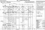
Here's the 92 Bronco Frame dimensions in mm (other years similar, exc. for "front crumple zone")
"The F-Series and Bronco frames are made of all steel channel with replaceable steel
crossmembers.
The following illustrations serve as guides to the removal and installation of frame (5005) and crossmembers.
Frame and Crossmembers, F-150, F-250, F-350, F-Super Duty Chassis Cab and Bronco
Item Part Number Description
1 5028 Crossmember, No. 3
2 5005 Frame
3 N801107-S100 Nut
4 N605919-S2 Bolt
5 5C128 Crossmember
6 5030 Crossmember, No. 4
7 N647096 Rivet
8 5135 Crossmember, No. 4 Reinforcement
9 N647097 Rivet
A — Tighten to 34-46 Nm
(25-34 Lb-Ft)
Misalignment of frame (5005) is the result of damaged components.
Before checking frame alignment, inspect all frame members for damage, cracks, twists, or bends.
Check all welded connections for cracks. Inspect all rivets, bolts, and body support brackets for looseness.
Make all necessary repairs or replacements.
Diagonal or X-Frame Checking Method
NOTE: An alternate method of checking frame alignment is to use a frame gauge.
Frame alignment can be checked without removing the body from the frame (5005) by using the diagonal or X-frame checking method.
This method should be used to identify misalignment prior to any attempt to straighten a frame.
Place the vehicle on a clean, level floor and set the parking brake.
Select at least four points along the left frame side rail (5015) and transfer these points to the floor with a plumb bob. If desired, paper can be taped on the floor along both sides of the vehicle below the frame. Mark the points on the floor as accurately as possible.
Locate the corresponding points along the right frame side rail (5016) and transfer these points to the floor in the same manner.
Move the vehicle away from the marks on the floor, and measure diagonally between all points on the floor. Both measurements should be equal within 6.35mm (1/4 inch).
Measure between corresponding points parallel to the frame side rails. These measurements should be within 3.18mm (1/8 inch) of each other.
The squareness of the frame side rail web to the floor at the spring hangers and at the steering gear mounting location should be within 1.59mm (1/16 inch). The squareness of the frame side rail web to the floor at all other points should be within 3.18mm (1/8 inch). The web and ****** should be square at all other points within 3.18mm (1/8 inch).
Any point on one side rail should be within 3.18mm (1/8 inch) ahead, behind, above, or below the corresponding point on the opposite side rail. The frame side rail should not be bowed more than 3.18mm (1/8 inch) for each 2540mm (100 inches) of frame length. The overall width of the frame should not vary more than 3.18mm (1/8 inch).
An alternate method of checking frame alignment is to use Rotunda Laser Measuring System 073-00451 or equivalent.
Drilling Precautions
CAUTION: Do not drill holes in the frame flanges. This will reduce the strength of frame (5005).
If a hole must be drilled in the frame, make sure that it meets all of the following requirements:
The hole is located in the upper half of the frame.
The edge of the drilled hole and the edge of the nearest hole are at least 25mm (1 inch) apart.
The edge of the drilled hole is at least 25mm (1 inch) from the edge of the ******.
The drilled hole is not adjacent to any other existing brackets or components of frame.
Welding Precautions
CAUTION: Disconnect the battery ground cable (14301) before using any electric welding equipment.
All welding on frame must be done with electric welding equipment, and the heat should be kept in a small area to prevent change in hardness of the metal. Do not use gas welding equipment. A double reinforcement must be added to frames where heat or weld is applied to the area to be repaired. The welds are to run lengthwise along the reinforcement when a reinforcement is to be welded to the frame side rail.
Frame Strength Identification
F-Series, F-Super Duty Chassis Cab and Bronco all use a 36,000 psi steel frame.
Frame Straightening
Misalignment of frame can be corrected by straightening the out-of-line parts or by replacing the crossmembers, braces, or brackets if they are badly damaged.

WARNING: DO NOT STRAIGHTEN FRONT FRAME RAIL CONVOLUTES.

Straightening should be attempted on frames that fail to meet specifications of the diagonal checking method or where damage is visually apparent.
However, to prevent internal stresses in the metal, frame straightening should be limited to parts that are not severely bent. If heat is needed to straighten a frame member, keep the temperature below 649°C (1200°F) (a dull red glow). Excessive heat may weaken the metal in the frame members and cause permanent damage.
Frame Reinforcing
After a bent frame member has been straightened, inspect the member closely for cracks. If any cracks show, the frame member should be reinforced or replaced.
Reinforcements should be made from angle or flat stock of the same material and thickness as the frame member being reinforced, and should extend a minimum of 152.40mm (6 inches) to either side of the crack. Ideally, the reinforcement should be cut from the corresponding area of a similar frame.
Weld Attachment
To ensure a quality repair, adhere to the following procedure if it is necessary to weld reinforcements to the frame.
Wire brush the area around the crack to remove the paint, grease, mud, etc., and to expose the crack completely and ensure good weld adhesion.
To stop the crack from spreading, drill a 6.35mm (1/4-inch) hole at a point 12mm (0.50 inch) beyond the root of the crack.
Grind out the full length of the crack to the hole to form a V-shaped slot with the base of the V-slot contacting the reinforcement.
The base of the V-slot should have at least a 1.52mm (0.06-inch) opening to ensure weld penetration to the reinforcement when welding the crack.
Drill clearance holes in the reinforcements to clear rivet heads and bolt heads or nuts where necessary.
In the event that repair is required on more than one frame surface (i.e., a ****** crack that extends into the web), two pieces of flat stock (one for each surface) should be utilized and welded together where they join. The web reinforcement should be a minimum of 76.20mm (3.0 inches) high and have a 63.50mm (2.5-inch) radius at each of the two corners.
Completely clean the surface of frame under and around the reinforcements.
Clamp the reinforcements securely to the frame prior to welding.
Weld the reinforcement all around after welding the crack V-slot.
The ****** edge weld should be ground smooth after all pit holes have been filled by the weld.
If a damaged bolted-on frame bracket is to be replaced, the new bolts, washers, and nuts should be of the same specifications and bolt torques as the original parts.
In cases where it is necessary to remove rivets, replace them with Property Class 9.8 metric (Grade 8) nuts, bolts and washers of the next larger size (i.e., for 3/8-inch diameter rivets use 7/16-inch bolts, for 7/16-inch diameter rivets use 1/2-inch bolts). This requires line drilling of the holes to the same diameter as the new bolt (i.e., either 0.437 diameter or 0.500 diameter).
Frame Member Replacement
If a damaged frame member is to be replaced, new bolts, Property Class 9.8 metric (Grade 8) fasteners and rivets required for replacement of parts should be of the same specifications as the original bolts or rivets. In cases where it is necessary to substitute a bolt for a rivet, use the next larger size bolt.
TORQUE SPECIFICATIONS Description Nm Lb-Ft
Bolt, Shock Bracket 118-122 88-89
Nut, Crossmember No. 1 188-192 139-141
Bolt, Crossmember No. 4 Reinforcement (F-150) 34-46 25-34
Nut, Crossmembers No. 2, 3, 4, 6, and 7 (Where Required) 60-95 44-70
Steering Shaft to Steering Gear 41-57 30-42
Bolt Steering Gear to Frame Rail 73-90 54-66
Nut Sector Shaft Arm to Steering Gear 280-310 170-228..."
by Ford
GL!
Al