Assistance needed with post engine swap mess

Disclaimer: Links on this page pointing to Amazon, eBay and other sites may include affiliate code. If you click them and make a purchase, we may earn a small commission.

OP
OP
S

smptx

New member
Joined
Jul 22, 2012
Messages
25
Reaction score
0
Thanks for all of the helpful information. I am missing the "Canister Purge Solenoid Valve (CanP/CPRV)", and cannot find a wiring harness plug which would plug into its solenoid. At this point, I do not care if the cruise control works as long as the cruise mechanism does not affect anything else. Also, your first picture shows a hose coming off the side of cruise unit and routing to just behind the throttle cable. I do not have any port to hook that hose into. Knowing I have the original harness and computer, what do you think should happen to the port coming off the side of throttle body? Block it?

The Bronco starts great after setting all night. After starting and allowing the thermostat to open, if you shut it down. It has a 10% chance of starting if accelerator all the way to floor. If it does start, sounds like it is running on 3 or 4 cylinders, real rough and then finally will sound like hitting on all 8 cylinders. Idles about 1200 RPM.


miesk5

96 Bronco 5.0
Staff member
Moderator
Joined
Oct 18, 2005
Messages
9,071
Reaction score
1,019
Location
Floating in the Pacific
yo,

re; "...your first picture shows a hose coming off the side of cruise unit and routing to just behind the throttle cable. I do not have any port to hook that hose into..."

Seal it and zip it somewhere

"...Knowing I have the original harness and computer, what do you think should happen to the port coming off the side of throttle body? Block it?..."

No, pull a CANP unit from a yard Bronco or truck

Wiring Diagram in an 89

bronco-1989-eec--pg-42.gif

Source: by SeattleFSB (Seattle FSB) at SuperMotors.net

See Connector C113?

Find it using this C101, C102, C106, C113, C114, C117, C122, C129, C134, C143, C158, C400, C401, C407, C408, C410, C414, C417 Location in Frame Rail Diagram

1990-component-location-view-15111.jpg

Source: by Seattle FSB (SeattleFSB) at SuperMotors.net


Rons beast

Active member
Joined
Dec 13, 2007
Messages
1,537
Reaction score
13
Location
Florida..in my mind , sitting on the beach
Have you corrected the ACT sensor issue? Sounds like the eec is getting signals that tell it the engine needs to be rich to start cold.

That is why you need to push the accelerator to the floor to start. That puts the eec in "open loop" and it ignores inputs, and goes to pre programed perimeters. The engine runs poor till the raw fuel is burned off and enough heat is dispenced to trigger the eec to closed loop and run based on sensor. inputs.

Hope you are making progress

M5 has you on the right track.

 
OP
OP
S

smptx

New member
Joined
Jul 22, 2012
Messages
25
Reaction score
0
My plan to correct the ACT is to either drill and tap (proper spot) the lower intake and install. Considering I still have the wiring harness and computer for the 89 302, the plan I am looking at right now is to replace the lower/upper intake and throttle body with one which belongs on the 89. I am not sure if it will mate up with the block, will it?. Not sure which block I have. 89? 91? 94? 95? If I can proceed with this route, I will have everything needed (I believe) to return it to factory specs.

Does this engine have a coolant temp sensor (for computer ops) AND a temperature sensor (for driver's temp gauge)?

Another million dollar question is: Someone told me that this model engine is notorious for the # 8 cylinder intake valve cracking. If this is true, then the # 8 will load up with fuel and cause the computer to create issues for the remaining 7 cylinders. The guy who told me this is a manager for a local "Brake Check" store and owns a 1985 model. Is this true? If so, would my engine's symptoms represent this # 8 problem?

I certainly hope this is not the case. Any way of verifying the # 8 is loading up with a bad intake valve without breaking down the engine? When I changed the plugs, the one pulled from # 8 had a normal residue (light brown) which indicates a normal burn. If true, I will have to pull the head and send to a machine shop - major major deal.

Thanks again . . .

 
Last edited by a moderator:

miesk5

96 Bronco 5.0
Staff member
Moderator
Joined
Oct 18, 2005
Messages
9,071
Reaction score
1,019
Location
Floating in the Pacific
yo,

re; "Does this engine have a coolant temp sensor (for computer ops) AND a temperature sensor (for driver's temp gauge)?"

YES

see Engine Coolant Temperature (ECT) Sensor Location pic; & Temperature Gauge Sending Unit; (GT40 lower intake manifold; same locations)

gt40-lower-intake.jpg

Source: by Gacknar

and

Positive Crankcase Ventilation (PCV) Vacuum Supply Hose Rerouting in 87-93 5.0 Bronco, F Series & vans;

MIESK5 NOTE; Includes 5.8;

THE PCV Valve remains in original position, we are changing the VACUUM Line Port

Failure of the #8 piston or the #8 rod or rod bearing; "...Failure of the #8 piston or the #8 rod or rod bearing in Ford 5.0L, V-8 gas engines. Solution: During engine installation, reroute the PCV valve vacuum supply hose. Follow these steps: Plug the 3/8" (pipe) thread hole in the rear of the plenum where the PCV valve hose is connected. Drill and tap a 3/8" pipe thread hole in the center of the plenum and thread the PCV connector into it. Reconnect the PCV valve vacuum supply hose to the new location. Be sure the drain hole in the Oil baffle is open. The Oil baffle is under the PCV location. Installers who have rerouted the PCV system and opened the baffle drain hole have not reported any #8 cylinder failures..."

Source: by fourstarengines.com via web.archive.org http://web.archive.org/web/20061025155759/http://www.fourstarengines.com/techtips3.htm

PCV Vacuum Supply Hose Rerouting Video in an 86 5.0

Source: by JKossarides ("The Bronco", Jean) at http://www.supermotors.net/registry/media/742778

PCV Vacuum Supply Hose Rerouting in 85-97 Bronco, F Series & vans; Failure of the #8 piston or the #8 rod or rod bearing with 5.0L and 5.8L engines. Failure of the rear piston, rod, or rod bearing (cylinders 5 & 8). After discussing the situation with several installers, the problem has been narrowed down to the PCV system. This picks up crankcase gasses from above the #8 cylinder and dumps into the back of the intake. Miesk5 NOTE; I Don't know where Ryan got the year range and #5 cylinder info from.. most likely is a typo....read more...

Source: by Ryan M (Fireguy50) at http://oldfuelinjection.com/files/Reroute_PVC.pdf

Oil Baffle pic in a 5.0

5.0pcvoil-baffle.jpg

Source: by miesk5 at SuperMotors.net

 
Last edited by a moderator:

Rons beast

Active member
Joined
Dec 13, 2007
Messages
1,537
Reaction score
13
Location
Florida..in my mind , sitting on the beach
Hey SM,

Regarding the coolent temp sensors M5 answered that in his post above.

The A. C. T. (Air charge temperature) should monitor temperature of the incomming air into the MAF (mass air flow ) sensor. That means it has to be in the air box after the air filter. Not in the manifold. If you have the original air box for the air filter there should already be a hole there for the sensor. OR what your are calling the ACT is not an ACT.

Regarding the #8 valve or any valve in this type of engine. What you were told is absolutly false. Or I should say I have no knowledge of the #8 intake valve being prone to cracking. If it did there is still no way extra fuel would be drawn into the cylinder. The injectors will spray only when the comp tells them to so no extra fuel would be drawn in. If you did have a cracked intake valve it would allow some of the compression and exhaust gass to seep back in to the intake, causing counter preasure and this would be seen on a vacuum gauge. Also the engine would run rough all the time.

A way of checking any valve in any engine is to get an adaptor to ***** an air line from an air compressor into the spark plug hole.

Turn the engine by hand to get that cylinder at TDC. ( both valves closed) apply air and listen for leakage in the intake or exhaust. Don't hear any? valves are good. hear hissing? = problem.

Good Luck

 
OP
OP
S

smptx

New member
Joined
Jul 22, 2012
Messages
25
Reaction score
0
The A. C. T. (Air charge temperature) should monitor temperature of the incomming air into the MAF (mass air flow ) sensor. That means it has to be in the air box after the air filter. Not in the manifold. If you have the original air box for the air filter there should already be a hole there for the sensor. OR what your are calling the ACT is not an ACT.
Ron:

Everything under the hood (computer, wiring harness, air box, etc) except engine, is a factory SD setup (except the MAF engine. Originally, the ACT sensor was in the intake manifold on the driver's top front side as should be for the 89 year model 302. In a perfect world, whoever did the engine swap with a newer style engine/intake (lower and upper), throttle body would have changed out the airbox, computer, wiring harness and everything else to match the engine swap. Unfortunately they did not. So what they did was tap into a pipe approx one inch above the coolant sensor and installed the ACT sensor. I verified it is the ACT sensor with a trace and color code of the wiring. My problem is witn the ACT is knwoing the logic needed to send proper signals to the EEC, I have a problem with it being subjected to hot coolant. The solutions I have been provided so far is to drill and tap the lower intake in an exact location where it should be located, buy a lower intake which already has the hole for the ACT, or route the sensor to the airbox. Because my setup (computer, wiring harness, etc) is still "Speed Density" (SD), I have reservations with routing to a SD airbox (non MAP.

Recap: My engine/intake/throttle body is out of a MAP vehicle transplanted into a SD environment. Whoever did the swap, did a half-assed job in "making it worK" and now I am sorting through the mess.

I really do appreciate the input and will monitor . . .

Mark

 
Last edited by a moderator:
OP
OP
S

smptx

New member
Joined
Jul 22, 2012
Messages
25
Reaction score
0
Update: We found a bad pin in the wiring connector for Coolant Temp Sensor. Repaired pin . . . Flooding problem solved . .. Still working on ACT senor issues. Unable to get 5 volts (only getting 3.5, bad EEC?) from ACT sensor wiring and find a way to mount it. Can’t find ANY wiring for CANP. Maybe this model did not have a electrically actuated CANP?


Elmo

Member
Joined
Dec 2, 2008
Messages
417
Reaction score
1
Location
Forsyth Georgia
it would seem to me that if your computer is speed density then there would be no need to provide it with inputs for the Mass air flow type system. so i wonder if you even need the ACT at all

 
OP
OP
S

smptx

New member
Joined
Jul 22, 2012
Messages
25
Reaction score
0
it would seem to me that if your computer is speed density then there would be no need to provide it with inputs for the Mass air flow type system. so i wonder if you even need the ACT at all
SD setup requires ACt sensor. Not indending to provide it with MAF inputs. I believe the big culprit is the ACT system. Sensor is new and passes testing. Not sure if EEC is sending right voltage (5 volts) to ACT sensor.

Second million dollar question: The ACT sensor has a brass base which is suppose to be installed in the aluminum lower intake in a predetermined hole. Since my frankenstein engine has the newer style lower intake, no hole. The question is: If the sensor was properly installed, does the brass base in contact with the aluminum lower intake serve as a "required ground" for the sensor to operate properly? The reason for the question is someone on a different formum drilled a hole in their plastic airbox and left it there with no side affects. Hard to believe considering the EEC has a temperature range programmed in software for ACT sensor signals. Lower intake gets warmer than platic airbox . . . .

 
Last edited by a moderator:

miesk5

96 Bronco 5.0
Staff member
Moderator
Joined
Oct 18, 2005
Messages
9,071
Reaction score
1,019
Location
Floating in the Pacific
Second million dollar question: The ACT sensor has a brass base which is suppose to be installed in the aluminum lower intake in a predetermined hole. Since my frankenstein engine has the newer style lower intake, no hole. The question is: If the sensor was properly installed, does the brass base in contact with the aluminum lower intake serve as a "required ground" for the sensor to operate properly? The reason for the question is someone on a different formum drilled a hole in their plastic airbox and left it there with no side affects. Hard to believe considering the EEC has a temperature range programmed in software for ACT sensor signals. Lower intake gets warmer than platic airbox . . . .

yo,

No Ground needed for ACT

From EEC PIN 25 to ACT Y/R

From ACT BK/W to Splice BK/W to SIG Return in EEC PIN 46 BK/W

 
OP
OP
S

smptx

New member
Joined
Jul 22, 2012
Messages
25
Reaction score
0
yo,

No Ground needed for ACT

From EEC PIN 25 to ACT Y/R

From ACT BK/W to Splice BK/W to SIG Return in EEC PIN 46 BK/W
M5, thanks for the ALL of your help and insights! I am pulling the lower intake today, going to drill and tap in proper place for ACT sensor. Any idea what size hole the ACT sensor requires? Specifics on the thread for the die? Also. Looking for the color codes for wires which run the CANP solenoid. Not sure if it is electrically actuated for this setup. Pin numbers on EEC for CANP?

Mark


Rons beast

Active member
Joined
Dec 13, 2007
Messages
1,537
Reaction score
13
Location
Florida..in my mind , sitting on the beach
Hey Mark,

I didn't realize you were working on a SD motor. I still thought it was a 91 with MAF. Someone didn't do a Half ass job they did a total ass job.

Kudos to you for all the work to sort this thing out. When this is all done I was going to suggest it get pinned to show how to do this type conversion. However I still think the best advice regarding this swap is:"DON'T" .

Good Luck


miesk5

96 Bronco 5.0
Staff member
Moderator
Joined
Oct 18, 2005
Messages
9,071
Reaction score
1,019
Location
Floating in the Pacific
M5, thanks for the ALL of your help and insights! I am pulling the lower intake today, going to drill and tap in proper place for ACT sensor. Any idea what size hole the ACT sensor requires? Specifics on the thread for the die? Also. Looking for the color codes for wires which run the CANP solenoid. Not sure if it is electrically actuated for this setup. Pin numbers on EEC for CANP?

Mark

Yo MARK,

Validate this info before your drill/tap; 3/8" x 18NPT

Calibration number (also called catch code

Based on VECI Label Info I gave you on page 1;

Ford part Number in Vehicle Emission Control Information (VECI) Decal; Contains Vacuum Diagram & Calibration Parts List for 88 & UP. On-Line for Free at Ford. Click "Quick Guides" in left panel; Scroll to & CLICK VECI Labels "Provides Vehicle Emission Control Information (VECI) and a related calibration parts list." Enter applicable info (need to know your Calibration number (also called catch code) from your B-pillar sticker). Vacuum Diagram is the same as the one on the core support or hood or air filter cover. Suggest Right Clicking this Hot Link & Open in New Window

http://www.motorcraftservice.com/pubs/content/~WCKL50/~MUS~LEN/CKL5001.htm

___

CANP Pin is 31

http://oldfuelinjection.com/truckpinouts.html

BUT NOW I SEE that most wiring diagrams have 5.8 7.5 ONLY!

Wiring Diagram in an 89

bronco-1989-eec--pg-42.gif

by SeattleFSB

CANP GY/Y to PIN 31

From CaNP R to Splice S140 to EEC Power Relay

 
OP
OP
S

smptx

New member
Joined
Jul 22, 2012
Messages
25
Reaction score
0
89 Ford FS Bronco 5.0 Eddie Bauer Auto trans with OD. Installing new distributor. Not sure which dizzy gear - steel or cast iron? Called local Ford dealer provided VIN, still not sure. Been advised if wrong gear metal selected, could cause serious damage. Any ideas?

 
Last edited by a moderator:

Rons beast

Active member
Joined
Dec 13, 2007
Messages
1,537
Reaction score
13
Location
Florida..in my mind , sitting on the beach
why are you changing the dist. ?

If you have to change it,why not switch the gear from the old dizzy to the new one.

If the motor has been changed, you don't know for sure if the cam is original. If it is, are you still not up in the air about what year and whatnot?

BUT you do know that the existing gear works with the cam, right?

I would use the old gear unless it is really fudged up.

 
Last edited by a moderator:

miesk5

96 Bronco 5.0
Staff member
Moderator
Joined
Oct 18, 2005
Messages
9,071
Reaction score
1,019
Location
Floating in the Pacific
yo,

a new distr is avail at our SPONSOR, Jeff's Bronco Graveyard for only $65.00 http://broncograveyard.com/bronco/c-1017-distrubutors-ignition.html'>http://broncograveyard.com/bronco/c-1017-distrubutors-ignition.html

Cast Iron Gear

Jeff at the Bronco Graveyard has offered a 2% discount to members of The BroncoZone for on line orders. To get your discount, enter the discount code BZMEMBER. Also you must include your BroncoZone User Name with the order.

-----------

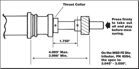
Cam Gear Failure Replacement Units Installed in New or Remanufactured Engines; Ford gear-type distributors. Replacement units installed in new or remanufactured engines experience distributor or cam gear failure. Failure to pre-**** distributor gear, prime oil pump, possible mismatch of gear and camshaft material, or inadequate oil pressure. Before installing distributor, **** distributor gear with grease and prime oil pump. Prime pump by using a drill with an intermediate shaft from an oil pump attached. Operate drill in a clock-wise direction until oil pressure develops. Or disable engine so it won't start then crank in short intervals until oil pressure develops. Do not tap starter or crank engine to position gear teeth. After installation check for up and down play of distributor shaft (must be between .015 and .030). Check camshaft end play for proper specification. If cam is changed it is very important that cam and gear material match. Steel distributor gears must only be used with roller camshafts, cast iron distributor gears only with cast iron camshafts.

Source: by CARDONE®

http://cds.activant.com/C2C/C01/78/740/946530136.pdf

see pics of gear, good, worn & bronken teeth

======

Cam Gear; "...It is easy to replace a PIP Sensor, but if you don't have access to an arbor press, don't do it. The potential for gear tooth damage, improper cam gear mesh, or a loose press fit stressing the roll pin can create catastrophic consequences. Below is what happens when you have an improper mesh between the cam gear and distributor gear which was amplified by the resistance of the Ford wet sump design. The Roller Cam gear faired even worse. Distributor gear removal and replacement is not something to be taken lightly. The tightness of the fit to the shaft, exact gear installation height, roll pin fit and initial lubrication are critical.." see diagram

Source: by Seattle FSB (SeattleFSB)

cam-gear-installation.jpg

Gear Removal & Installation

Source: by Ford

See for a LIST of all Gears, most are marked "Not Available" so, use google for pn.

http://www.fordracingparts.com/parts/part_details.asp?PartKeyField=7533

Such as:

M-12390-E Bronze Bronze with

Blue Stripe 1.249" 0.531" All 302 hydraulic (flat or roller) tappet engines with EFI.

All 351W engines. (1)

Bronze gears can be used with either cast iron or billet steel camshafts. They are usually recommended by manufacturers of aftermarket billet steel solid roller tappet camshafts. Since the bronze is softer than cast iron or steel, it will wear at a faster rate.

Polymer gears are compatible with all camshafts.

Cast iron gears are compatible with cast iron camshafts (hydraulic or solid flat tappet type).Steel gears are compatible with billet steel camshafts (hydraulic roller tappet type).

IMPORTANT INSTALLATION NOTE:


1Distributor gears do not have pre-drilled holes.

See instructions included with part, call the Techline (1-800-FORD788) for a faxed copy, or visit fordracingparts.com.


M-12390-A/B/C/D/E/F/G/H/J/K/L

Distributor Gear

INSTALLATION INSTRUCTIONS

http://www.fordracingparts.com/download/instructionsheets/FordInstShtM-12390-ABCDEFGHJKL.pdf


FORD RACING 302/351W BRONZE DISTRIBUTOR GEAR M-12390-E

http://www.ebay.com/itm/FORD-RACING-302-351W-BRONZE-DISTRIBUTOR-GEAR-M-12390-E-/270205400626

$65.00


a new distr is avail at our SPONSOR, Jeff's Bronco Graveyard for only $65.00 http://broncograveyard.com/bronco/c-1017-distrubutors-ignition.html

 
OP
OP
S

smptx

New member
Joined
Jul 22, 2012
Messages
25
Reaction score
0
Update: Found replacement upper intake and TB which goes with this engine/vac lines/ emissions. Changing those items next few days. Fount lower intake bolts "finger tight" . . . Hmm, this would cause all kinds of problems. Also did the relocation of ACT sensor @ # 5 runner while lower intake off engine. Will be relocating PVC stub on this replacement Upper per M5. Wanting to change distributor while all apart. @ Ronsbeast, you are correct, I do not know which cam is in this engine. Could keep original gear or just not replace the distributor. @ M5 thanks for all of your resources.

I just about have all the emission parts needed to make this engine "right". I am lack the following:

Still can not find ANYTHING in wiring harness which would plug into a "CANP", can't find any cut, burnt off wires either. So I am at a stand still from the air pump back to the TB. I do not know what goes on the other end of tube headed back to TB. A purge valve? If so, not wiring. Does an 89 5.0 have a electrically actuated purge valve? I get conflicting info from the diagrams, etc. Most schematics show electric valve for 5.8 and 7.? L engines.

Seems like something simple, but yet complicated.

 
OP
OP
S

smptx

New member
Joined
Jul 22, 2012
Messages
25
Reaction score
0
Looking for exact bolt size - crankshaft pully 89 FSB 5.0L need to buy socket and extension to move crank to TDC

 
Last edited by a moderator:

Members online

No members online now.

Latest posts

Forum statistics

Threads
22,521
Messages
135,985
Members
25,127
Latest member
JohnK
Top