My in-fuel pump fitting for rail pump is broken-------What 90-degree fuel fitting fits that----Is the fuel line 5/16 - I'm guessing here---if that was standard size on a 1989 Bronco then what would the barbed fitting end be 3/8 barb to fit a 5/16 line---- so would be 5/16-3/8 fitting?? need some help
You are using an out of date browser. It may not display this or other websites correctly.
You should upgrade or use an alternative browser.
You should upgrade or use an alternative browser.
Rail fuel pump fitting
- Thread starter captsb890
- Start date
Disclaimer: Links on this page pointing to Amazon, eBay and other sites may include affiliate code. If you click them and make a purchase, we may earn a small commission.
Motech
Well-known member
What engine?
Motech
Well-known member
Here's the text of a Ford TSB addressing nylon fuel line repair:
9228FORD02
Article No. 92-12-16
DATE: 06-03-92
FUEL LINES-NYLON-SERVICING PROCEDURE
LIGHT TRUCK:
1985-92 F-150-350 SERIES
1986-90 BRONCO II
1986-92 AEROSTAR, BRONCO, ECONOLINE, RANGER
1988-92 F SUPER DUTY 1991-92
EXPLORER
ISSUE:
Metal fuel lines and connectors have been replaced with nylon lines and connectors on the subject vehicles. A procedure has been developed for servicing damaged nylon fuel lines.
ACTION:
If a nylon fuel line requires service, use the following procedure.
FUEL SYSTEM SERVICE PROCEDURE FOR NYLON FUEL TUBES AND PUSH CONNECT FITTINGS
FUEL LINES AND HOSES
WARNING:
FUEL SUPPLY LINES ON VEHICLES WITH FUEL INJECTED ENGINES WILL REMAIN PRESSURIZED FOR LONG PERIODS OF TIME AFTER ENGINE SHUT DOWN WHICH COULD RESULT IN PERSONAL INJURY. THE PRESSURE MUST BE RELIEVED, AS OUTLINED PER THE FUEL SYSTEM PRESSURE RELIEF PROCEDURE, BEFORE SERVICING THE FUEL SYSTEM. READ ALL CAUTIONARY NOTES PRIOR TO RELIEVING THE PRESSURIZED FUEL SYSTEM.
FUEL TUBES - PLASTIC (NYLON)
CAUTION:
FORD APPROVED NYLON FUEL TUBING IS MADE FROM MATERIAL WHICH HAS BEEN TESTED AND PROVEN TO BE ACCEPTABLE FOR USE WITH COMMERCIALLY AVAILABLE FUELS. IT IS ALSO RESISTANT TO MOST ENVIRONMENTAL CONDITIONS. AVOID USING ALTERNATE TUBING MATERIALS. USE OF NON-APPROVED TUBING COULD POSE A HAZARD IN SERVICE.
CAUTION:
PLASTIC FUEL TUBES MUST NOT BE REPAIRED USING HOSE AND HOSE CLAMPS. PUSH CONNECT FITTINGS CANNOT BE REPAIRED EXCEPT TO REPLACE THE RETAINING CLIPS. IF THE PLASTIC TUBES OR PUSH CONNECT FITTINGS BECOME DAMAGED AND LEAK, APPROVED SERVICE PARTS MUST BE USED TO SERVICE THE FUEL LINES.
MAJOR SERVICE OPERATIONS - FUEL LINES
Vehicles equipped with nylon fuel tubes and push connect fittings have three (3) typesDS) OF NYLON FUEL LINES CANNOT BE REPAIRED USING STRAIGHT TUBING. STRAIGHT SERVICE TUBING WILL KINK IF BENT. FORMED NYLON FUEL LINE IS REOUIRED TO REPLACE THE DAMAGED SECTION.
SPLICING NYLON TO NYLON
1. Relieve the fuel system pressure as outlined in the Service Manual. Read the previously cited Warning prior to relieving the pressurized fuel system.
2. Cut out the damaged section of tubing (straight non-formed sections only) and retain as a guide.
3. Cut a section of nylon service tubing, type 11 or 12, of the same diameter and length as the damaged section of tubing.
NOTE: TYPE 11 OR 12 NYLON SERVICE TUBING IS AVAILABLE IN 6.3MM (1/4"), 7.9MM (5/16") AND 9.5MM (3/8") DIAMETER SIZES.
4. Select the proper nylon barbed connector(s) for completing the splice...
^ 7.9mm (5/16") - Part Number (N806120-S)
^ 9.5mm (3/8") - Part Number (N806119-S)
Two (2) in-line connectors are required for each splice.
NOTE:
TO MAKE INSERTION OF THE BARB CONNECTORS INTO THE NYLON LINE EASIER, THE TUBE END MAY BE SOAKED IN A CUP OF BOILING WATER FOR ONE (1) MINUTE BEFORE PUSHING THE BARB CONNECTOR INTO THE NYLON. USE ROTUNDA TOOL 134-000001 OR EQUIVALENT TO ASSIST IN ASSEMBLY.
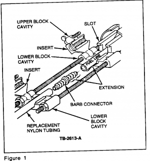
5. Set up Rotunda Tool 134-000001 for in-line splice as shown in Figure 1.

a. Select the proper inserts for the fuel line size and install into both sets of upper and lower block cavities.
b. Connect the block cavity to the ratcheting rod of the Rotunda Tool with the slot in line with the slot in the ratcheting tool barrel
c. Install both sets of upper and lower block cavities to the threaded rods of the ratcheting tool, Figure 1.

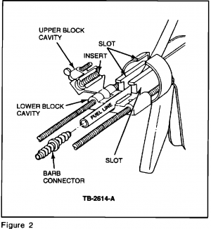
d. Install one fuel line into the lower block cavity closest to the ratcheting end of the tool so that the extension of the fuel line is slightly greater than the barb length of the connector, Figure 2.
e. Route the fuel line through the slot in the tool, Figure 2.
f. Close the upper block cavity onto the lower block cavity and tighten the thumb s-crew (JHC) securely.
g. Place the replacement tubing in the forward lower block cavity and repeat Steps d and e.
h. Place the barb connector between the ends of the lines to be spliced and ratchet the tool until the nylon line has covered all three (3) barbs of the connector on both ends.
i. After completing the splice, unscrew the thumb screws and release the lines. Repeat Steps d through h on the opposite line end to complete the splice.

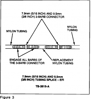
6. The completed fuel line splice is shown in Figure 3.
7. Install any remaining clips which were removed for this service. Check to be sure the fuel lines are secure in the original clips.
8. Start the engine and check for leaks.
PART NUMBER PART NAME CLASS
N806119-S Connector - Hose Push CG
Connect (3/8")
N806120-S Connector - Hose Push CG
Connect (5/16")
NYLON FUEL LINES - SERVICING PROCEDURE9228FORD02
Article No. 92-12-16
DATE: 06-03-92
FUEL LINES-NYLON-SERVICING PROCEDURE
LIGHT TRUCK:
1985-92 F-150-350 SERIES
1986-90 BRONCO II
1986-92 AEROSTAR, BRONCO, ECONOLINE, RANGER
1988-92 F SUPER DUTY 1991-92
EXPLORER
ISSUE:
Metal fuel lines and connectors have been replaced with nylon lines and connectors on the subject vehicles. A procedure has been developed for servicing damaged nylon fuel lines.
ACTION:
If a nylon fuel line requires service, use the following procedure.
FUEL SYSTEM SERVICE PROCEDURE FOR NYLON FUEL TUBES AND PUSH CONNECT FITTINGS
FUEL LINES AND HOSES
WARNING:
FUEL SUPPLY LINES ON VEHICLES WITH FUEL INJECTED ENGINES WILL REMAIN PRESSURIZED FOR LONG PERIODS OF TIME AFTER ENGINE SHUT DOWN WHICH COULD RESULT IN PERSONAL INJURY. THE PRESSURE MUST BE RELIEVED, AS OUTLINED PER THE FUEL SYSTEM PRESSURE RELIEF PROCEDURE, BEFORE SERVICING THE FUEL SYSTEM. READ ALL CAUTIONARY NOTES PRIOR TO RELIEVING THE PRESSURIZED FUEL SYSTEM.
FUEL TUBES - PLASTIC (NYLON)
CAUTION:
FORD APPROVED NYLON FUEL TUBING IS MADE FROM MATERIAL WHICH HAS BEEN TESTED AND PROVEN TO BE ACCEPTABLE FOR USE WITH COMMERCIALLY AVAILABLE FUELS. IT IS ALSO RESISTANT TO MOST ENVIRONMENTAL CONDITIONS. AVOID USING ALTERNATE TUBING MATERIALS. USE OF NON-APPROVED TUBING COULD POSE A HAZARD IN SERVICE.
CAUTION:
PLASTIC FUEL TUBES MUST NOT BE REPAIRED USING HOSE AND HOSE CLAMPS. PUSH CONNECT FITTINGS CANNOT BE REPAIRED EXCEPT TO REPLACE THE RETAINING CLIPS. IF THE PLASTIC TUBES OR PUSH CONNECT FITTINGS BECOME DAMAGED AND LEAK, APPROVED SERVICE PARTS MUST BE USED TO SERVICE THE FUEL LINES.
MAJOR SERVICE OPERATIONS - FUEL LINES
Vehicles equipped with nylon fuel tubes and push connect fittings have three (3) typesDS) OF NYLON FUEL LINES CANNOT BE REPAIRED USING STRAIGHT TUBING. STRAIGHT SERVICE TUBING WILL KINK IF BENT. FORMED NYLON FUEL LINE IS REOUIRED TO REPLACE THE DAMAGED SECTION.
SPLICING NYLON TO NYLON
1. Relieve the fuel system pressure as outlined in the Service Manual. Read the previously cited Warning prior to relieving the pressurized fuel system.
2. Cut out the damaged section of tubing (straight non-formed sections only) and retain as a guide.
3. Cut a section of nylon service tubing, type 11 or 12, of the same diameter and length as the damaged section of tubing.
NOTE: TYPE 11 OR 12 NYLON SERVICE TUBING IS AVAILABLE IN 6.3MM (1/4"), 7.9MM (5/16") AND 9.5MM (3/8") DIAMETER SIZES.
4. Select the proper nylon barbed connector(s) for completing the splice...
^ 7.9mm (5/16") - Part Number (N806120-S)
^ 9.5mm (3/8") - Part Number (N806119-S)
Two (2) in-line connectors are required for each splice.
NOTE:
TO MAKE INSERTION OF THE BARB CONNECTORS INTO THE NYLON LINE EASIER, THE TUBE END MAY BE SOAKED IN A CUP OF BOILING WATER FOR ONE (1) MINUTE BEFORE PUSHING THE BARB CONNECTOR INTO THE NYLON. USE ROTUNDA TOOL 134-000001 OR EQUIVALENT TO ASSIST IN ASSEMBLY.
5. Set up Rotunda Tool 134-000001 for in-line splice as shown in Figure 1.

a. Select the proper inserts for the fuel line size and install into both sets of upper and lower block cavities.
b. Connect the block cavity to the ratcheting rod of the Rotunda Tool with the slot in line with the slot in the ratcheting tool barrel
c. Install both sets of upper and lower block cavities to the threaded rods of the ratcheting tool, Figure 1.

d. Install one fuel line into the lower block cavity closest to the ratcheting end of the tool so that the extension of the fuel line is slightly greater than the barb length of the connector, Figure 2.
e. Route the fuel line through the slot in the tool, Figure 2.
f. Close the upper block cavity onto the lower block cavity and tighten the thumb s-crew (JHC) securely.
g. Place the replacement tubing in the forward lower block cavity and repeat Steps d and e.
h. Place the barb connector between the ends of the lines to be spliced and ratchet the tool until the nylon line has covered all three (3) barbs of the connector on both ends.
i. After completing the splice, unscrew the thumb screws and release the lines. Repeat Steps d through h on the opposite line end to complete the splice.

6. The completed fuel line splice is shown in Figure 3.
7. Install any remaining clips which were removed for this service. Check to be sure the fuel lines are secure in the original clips.
8. Start the engine and check for leaks.
PART NUMBER PART NAME CLASS
N806119-S Connector - Hose Push CG
Connect (3/8")
N806120-S Connector - Hose Push CG
Connect (5/16")
Last edited:
its a 351 W --fuel injection all I need to know is what size fitting that is---it's a 90 degree---so is it a 5/16 to 5/16 or is it 5 /16 to 3/8 or - the book shows a 5/16 connecter but not the barbed end---size-?--on a typical rail pump is that 1/4 tube-?-----The book shows the old ford number of 9J323---for the 90 and 9J322 for the straight fitting---What engine?
Motech
Well-known member
Pipe specs will mess you up. They measure inner diameter. Go with outer line spec of ⅜ for supply line as @Tiha noted with barbed line connectors. Pipe fittings will reduce inner diameter way to much and you'll choke off your fuel delivery under loads.on a typical rail pump is that 1/4 tube-?
Similar threads
- Replies
- 18
- Views
- 1K
- Replies
- 10
- Views
- 2K
