You are using an out of date browser. It may not display this or other websites correctly.
You should upgrade or use an alternative browser.
You should upgrade or use an alternative browser.
PSOM repair
- Thread starter ryeder
- Start date
Disclaimer: Links on this page pointing to Amazon, eBay and other sites may include affiliate code. If you click them and make a purchase, we may earn a small commission.

Attachments

Yo rydeer,
PSOM REPLACEMENT in F150 by Brent D @ PSOM REPLACEMENT F150 1995 photo series, step by step
Same for our Broncos.
"...The instrument cluster requires special handling to avoid damaging internal components. The cluster MUST be kept FACE UP or in the in-vehicle position. Leaving the cluster face down may result in a loss of dampening fluid used in the gauges. The lost fluid could stain the cluster face or result in excessive pointer waver..."; by Ford
johnnyreb
Well-known member
Yo rydeer,
PSOM REPLACEMENT in F150 by Brent D @ PSOM REPLACEMENT F150 1995 photo series, step by step
Same for our Broncos.
"...The instrument cluster requires special handling to avoid damaging internal components. The cluster MUST be kept FACE UP or in the in-vehicle position. Leaving the cluster face down may result in a loss of dampening fluid used in the gauges. The lost fluid could stain the cluster face or result in excessive pointer waver..."; by Ford
johnnyreb
Well-known member
What a dumb way to make something---another way to make sure they make money off of a person. Another REASON I don,t like modern stuff. Thank Al . Hope you are doing better.
johnnyreb
Well-known member
Me to . When they started doing away with points-and started with electronic box made me mad. I changed the distributors in my 75 ford f-600 and both my 78 broncos.Another reason I'm selling off every vehicle I have that was manufactured after 1980. Y'all have a great holiday weekend.
johnnyreb
Well-known member
Me to . When they started doing away with points-and started with electronic box made me mad. I changed the distributors in my 75 ford f-600 and both my 78 broncos. Alot safer too.
I need of some ideas. PSOM came back today and was installed. And, the intial problems, ie...speedo not working, shifts hard, of light flashing...did not go away. If the PSOM was toast, the company would of indicated that. There are no codes showing and no idiot lights on the dash lighting up. Tach and guages work. Grasping at straws here, but would it need a reset? Bad sensor? Wiring harness? Any info would be greatly appreciated.
Last edited:
Yo ryeder,
Vehicle Speed Sensor Insufficient or intermittent vehicle speed input. Powertrain control module aka computer, EEC V, detected a loss of vehicle speed signal during operation. Harsh engagements, firm shift feel, abnormal shift schedule, unexpected downshifts may occur at closed throttle, abnormal torque converter clutch operation or engages only at wide-open throttle. May flash transmission control indicator lamp and PSOM may flutter like a bee or worse.
•
Before buying any parts;
This problem could be caused by a # of things;
Check cab fuses 8 and 18;

If no 12 v on Supply Side of each; look in Power Distribution Box (Located under the hood on the drivers side fenderwell, on driver's side of the air cleaner housing)
and check **** FUSES 10 and 20

Fuse Position Amps Circuits Protected
1 20 Radio
2 30 4WABS Relay No. 1
3 30 Horn Relay, Daytime Running Lamps (DRL), Multi-Function Switch, Speed Control
4 25 Trailer Marker Lamps Relay, Trailer Backup Lamps Relay
5 15 Heated Oxygen Sensor (HO2S), Backup Lamps, 4WABS, Trailer Battery Charge Relay, Daytime Running Lamps (DRL), Speed Control
6 10 Trailer Right Stop/Turn Lamps
7 10 Trailer Left Stop/Turn Lamps
****-Fuse Position Amps Circuits Protected
8 30 4 WABS Relay No. 2
9 30 PCM Power Relay, Powertrain Control Module (PCM)
10 20 See Fuse 18 (IP Fuse Panel), Starter Relay
11 — Not Used
12 (Diode) 20 Ignition System, PCM Power Relay Coil
13 50 See Fuses 5, 9 and 13 (IP Fuse Panel)
14 30 Rear Window Defrost
15 50 See Fuses 1 and 7 (IP Fuse Panel) and Fuse 5
16 20 Fuel Pump Relay
17 50 See Fuses 2, 6, 11 and 17, ****-Fuse 22 and Circuit Breaker 14
18 30 Trailer Battery Charge Relay
19 40 Main Light Switch, Headlamps
20 50 See Fuses 4, 8 and 16 (IP Fuse Panel). Also See Circuit Breaker 12.
21 30 Trailer Electronic Brake Control Unit
22 20 Diode Current Flows from Fuse 22 to PCM Power Relay
Relay 1 Relay PCM Power Relay
Relay 2 Relay Fuel Pump Relay
Relay 3 Relay Horn Relay
Relay 4 Relay Trailer Marker Lamps Relay
Relay 5 Relay 4WABS Relay No. 2
_
bad vehicle speed sensor (VSS) (also called ABS,, DSS sensor) on the 8.8 (rear differential)/ or corroded Connector/ wires inside connector;
or cruddy/damaged tone ring in the 8.8. (Tone Ring Inspection in an 8.8; "...Take off the rear diff cover. Check the Ring Tone gear. It is located on the left hand side of the ring gear. Look to see if any of the teeth have been notched (from debris floating around in the diff.) Usually a spider gear. If the ring tone gear has been notched, it will need to be replaced to fix your speedo reading. Jack it up and rotate the tires to look for the teeth to be notched/broken/bent...") Source: by Bighibbi at FSB
Measure air gap between the VSS and exciter ring. It should be 0.38-0.51mm (0.015-0.020"). Check exciter ring runout per the same ring gear backface runout procedure of the appropriate model 1996 Powertrain/Drivetrain Service Manual, Section 05-00. Make sure the exciter ring is mounted correctly to the ring gear. If runout is more than 0.1mm (0.004"), perform the differential runout check per the procedure in the appropriate model 1996 Powertrain/Drivetrain Service Manual, Section 05-02A or 05-02D, to find cause and repair as needed
Bad 4WABS Module - It is located below ws wiper fluid/coolant recovery tank. So, the connector can be corroded by leaking fluid or its microprocessors took a dump as mine did and then did this 4WABS Control Module Bypass for PSOM Operation due to Bad 4WABS Control Module at 4WABS Module Connector; "...jumper 14 (CKT 530, LG/Y)to 21 (CKT 519 (LG/BK) & 39 (CKT 491 (O/LB)to 22 (CKT 523, R/PK)..."
Source: by Turbo Ghost at https://www.fullsizebronco.com/forum/7-1980-96-bronco-tech/138574-vss-speedo-question-2.html
Or a bad PSOM (Speedo)
bad wiring/shorts /connectors from VSS at firewall, at 4WABS Module and /or at PSOM and then onto the PCM
•
If neither a voltmeter nor frequency counter is available, vehicle speed control may be used as a good indicator. If it works normally, then the PSOM aka speedometer module is at least receiving a speed input signal and the wiring and sensor can be assumed to be good. Ensure tge speed control recall has been completed by Ford. Call local dealer or register and view status @ https://owner.ford.com & have VIN ready..
"Summary: ON CERTAIN PICKUP TRUCKS, PASSENGER VEHICLES, SPORT UTILITY VEHICLES, AND MOTOR HOMES CHASSIS, THE SPEED CONTROL DEACTIVATION SWITCH MAY, UNDER CERTAIN CONDITIONS, LEAK INTERNALLY AND THEN OVERHEAT, SMOKE, OR BURN. THIS COULD RESULT IN AN UNDERHOOD FIRE."
Use this guide by jowens1126 to confirm recall status @ https://www.fullsizebronco.com/foru...ruise-control-recalls-repair.html#post6530073
•
Speed Input Signal Test at PSOM connector in4 a 96 from 1996 F-150, F-250, F-350, Bronco, F-Super Duty Motorhome Chassis Workshop Manual; CAUTION: Before checking the continuity of any circuit, make sure there is no voltage present in the circuit prior to switching the test equipment to the resistance function to avoid damage to equipment. Refer to the test equipment user's manual for additional information. Connect Rotunda 88 Digital Multimeter 105-00053 or equivalent to Pin 4 (speed +) and Pin 5 (speed -). If available, a frequency counter may be connected to Pin 4 (speed in +) and Pin 5 (speed in -). Does the displayed frequency of the signal increase smoothly and continuously from 0 to approximately 667 Hz at approximately 48 km/h (30 mph)? OR does the voltage increase smoothly and continuously from 0 to approximately 3.5 volts as vehicle speed increases from 0 to approximately 48 km/h (30 mph)? NO-REPLACE instrument cluster. YES-SERVICE wiring. CHECK for open wiring. If no problems are found, REFER to Section 06-09A Brake System, Anti-Lock, Rear or Section 06-09B.Brake, Anti-Lock, 4-Wheel
Programmable Speedometer/Odometer Module Connector;
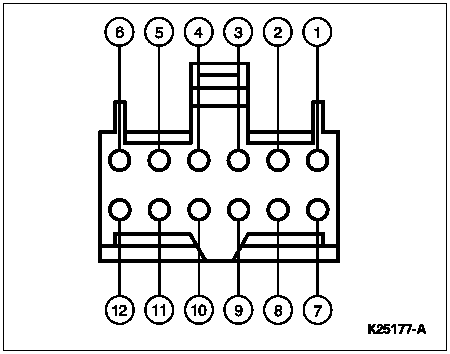
Image can't appear due to "securuity upgrade" or comcast bs, so here is the URL,
http://www.diesel-dave.com/vehic/manual/stj/images/k25177a.gif
BRONCO
Pin Number Circuit Circuit Function
1 54 (LG/Y) Battery Input
2 676 (PK/O) Ground
3 296 (W/P) Power (Hot in RUN)
4 491 (O/LB) 4WABS Signal Input
5 530 (LG/Y) 4WABS Signal Return
6 — Not Used
7 679 (GY/BK) Speed Output to Instrument Cluster, Speed Control Amplifier to Powertrain Control Module, and Compass
8 — Not Used
9 567 (LB/Y) PSOM Programming Connector
10 — Not Used
11 — Not Used
12 — Not Used
Source: by Ford via http://www.thedieselstop.com/faq/9497faq/maint/stj/stjd1017.htm
•
The locations of the connectors along the path from VSS to 4WABS and up to Instr Cluster & PSOM are;
C404 VSS On rear axle sensor (A7) Terminals: 02
•
C205 LH rear of engine compartment, in safety wall (Fire Wall) Terminals: 24 In-Line
•
C202F & M LH rear of engine compartment, in safety wall (A8) Terminal: 7 In-Line
•
C119 LH front corner of engine compartment on 4WABS control module (E10),Terminals: 40
•
O/LB to:
C202F & M LH rear of engine compartment, in safety wall (A8) Terminal: 7 In-Line
•
C252 Programmable Speedometer/Odometer Module (PSOM), Behind top LH side of I/P, on PSOM (A7) Terminal: 12 Color: B at Pins 4
•
LG/Y to Splice S107 Engine control sensor harness, from C119 near T/O to G101 (G101 RH side of Radiator support); to PSOM Pin 5
C202 F and M
and spliced to Ground G100 (BK)
G100 & G104 (tied together in diagram) G100 @ LH front of engine compartment, on upper radiator support
G100 Serves Component:
Fuel Pump Module
Inertia Fuel Shutoff
Misfire Sensor aka crankshaft position sensor
Misfire Sensor Shield
Output Shaft Speed (OSS) Sensor
Powertrain Control Module (PCM), 5.0L
G200 Behind bottom of RH cowl panel
Serves Component:
Air Bag Diagnostic Monitor
Electronic Shift Control Module
Instrument Cluster
Programmable Speedometer/Odometer Module (PSOM)
Remote/Keyless Entry Module
Speed Control Servo/Amplifier Assembly
From PSOM Pin 7 (GY/BK) to Splice S246 Main harness, near T/O to speed control amplifier to
C185 PK/O @ PCM 5.0L Powertrain Control Module (PCM) LH side of safety wall, on powertrain control module (PCM) (C10) Terminal: 104 Color: GY
C185, 5.8L Powertrain Control Module (PCM) LH side of safety wall, on powertrain control module (PCM) (C10) Terminal: 104 Color: GY
C185 @PCM to C202 F and M
Splice 216 to Ground G200, Instrument Cluster ground is inside passenger side kick panel
and on to C185 @ PCM PIN 58 (GY/BK) and from Pin 46 to MLPS (TR) Pin 2
Verify PCM & MLPS wiring & Pin numbers using following the WIRING DIAGRAMs by Mikey.
"...The correct PSOM vehicle speed signal to the PCM is an AC square wave that rises to 5 volts positive and drops back to 3 volts negative, with a frequency of about 120 Hz at 60 mph.
The sloping tops and bottoms on the waveform are normal, and don’t indicate a problem in the circuit..."
In a 92 F250, E4OD; Includes leaky capacitor on PSOM circuit board pic.
by Mike & Chris in Gear Magazine @ http://redirect.viglink.com/?format=...Qf6a0QL4GKHk1w
•
Vehicle Speed Sensor Insufficient or intermittent vehicle speed input. Powertrain control module aka computer, EEC V, detected a loss of vehicle speed signal during operation. Harsh engagements, firm shift feel, abnormal shift schedule, unexpected downshifts may occur at closed throttle, abnormal torque converter clutch operation or engages only at wide-open throttle. May flash transmission control indicator lamp and PSOM may flutter like a bee or worse.
•
Before buying any parts;
This problem could be caused by a # of things;
Check cab fuses 8 and 18;
If no 12 v on Supply Side of each; look in Power Distribution Box (Located under the hood on the drivers side fenderwell, on driver's side of the air cleaner housing)
and check **** FUSES 10 and 20
Fuse Position Amps Circuits Protected
1 20 Radio
2 30 4WABS Relay No. 1
3 30 Horn Relay, Daytime Running Lamps (DRL), Multi-Function Switch, Speed Control
4 25 Trailer Marker Lamps Relay, Trailer Backup Lamps Relay
5 15 Heated Oxygen Sensor (HO2S), Backup Lamps, 4WABS, Trailer Battery Charge Relay, Daytime Running Lamps (DRL), Speed Control
6 10 Trailer Right Stop/Turn Lamps
7 10 Trailer Left Stop/Turn Lamps
****-Fuse Position Amps Circuits Protected
8 30 4 WABS Relay No. 2
9 30 PCM Power Relay, Powertrain Control Module (PCM)
10 20 See Fuse 18 (IP Fuse Panel), Starter Relay
11 — Not Used
12 (Diode) 20 Ignition System, PCM Power Relay Coil
13 50 See Fuses 5, 9 and 13 (IP Fuse Panel)
14 30 Rear Window Defrost
15 50 See Fuses 1 and 7 (IP Fuse Panel) and Fuse 5
16 20 Fuel Pump Relay
17 50 See Fuses 2, 6, 11 and 17, ****-Fuse 22 and Circuit Breaker 14
18 30 Trailer Battery Charge Relay
19 40 Main Light Switch, Headlamps
20 50 See Fuses 4, 8 and 16 (IP Fuse Panel). Also See Circuit Breaker 12.
21 30 Trailer Electronic Brake Control Unit
22 20 Diode Current Flows from Fuse 22 to PCM Power Relay
Relay 1 Relay PCM Power Relay
Relay 2 Relay Fuel Pump Relay
Relay 3 Relay Horn Relay
Relay 4 Relay Trailer Marker Lamps Relay
Relay 5 Relay 4WABS Relay No. 2
_
bad vehicle speed sensor (VSS) (also called ABS,, DSS sensor) on the 8.8 (rear differential)/ or corroded Connector/ wires inside connector;
or cruddy/damaged tone ring in the 8.8. (Tone Ring Inspection in an 8.8; "...Take off the rear diff cover. Check the Ring Tone gear. It is located on the left hand side of the ring gear. Look to see if any of the teeth have been notched (from debris floating around in the diff.) Usually a spider gear. If the ring tone gear has been notched, it will need to be replaced to fix your speedo reading. Jack it up and rotate the tires to look for the teeth to be notched/broken/bent...") Source: by Bighibbi at FSB
Measure air gap between the VSS and exciter ring. It should be 0.38-0.51mm (0.015-0.020"). Check exciter ring runout per the same ring gear backface runout procedure of the appropriate model 1996 Powertrain/Drivetrain Service Manual, Section 05-00. Make sure the exciter ring is mounted correctly to the ring gear. If runout is more than 0.1mm (0.004"), perform the differential runout check per the procedure in the appropriate model 1996 Powertrain/Drivetrain Service Manual, Section 05-02A or 05-02D, to find cause and repair as needed
Bad 4WABS Module - It is located below ws wiper fluid/coolant recovery tank. So, the connector can be corroded by leaking fluid or its microprocessors took a dump as mine did and then did this 4WABS Control Module Bypass for PSOM Operation due to Bad 4WABS Control Module at 4WABS Module Connector; "...jumper 14 (CKT 530, LG/Y)to 21 (CKT 519 (LG/BK) & 39 (CKT 491 (O/LB)to 22 (CKT 523, R/PK)..."
Source: by Turbo Ghost at https://www.fullsizebronco.com/forum/7-1980-96-bronco-tech/138574-vss-speedo-question-2.html
Or a bad PSOM (Speedo)
bad wiring/shorts /connectors from VSS at firewall, at 4WABS Module and /or at PSOM and then onto the PCM
•
If neither a voltmeter nor frequency counter is available, vehicle speed control may be used as a good indicator. If it works normally, then the PSOM aka speedometer module is at least receiving a speed input signal and the wiring and sensor can be assumed to be good. Ensure tge speed control recall has been completed by Ford. Call local dealer or register and view status @ https://owner.ford.com & have VIN ready..
"Summary: ON CERTAIN PICKUP TRUCKS, PASSENGER VEHICLES, SPORT UTILITY VEHICLES, AND MOTOR HOMES CHASSIS, THE SPEED CONTROL DEACTIVATION SWITCH MAY, UNDER CERTAIN CONDITIONS, LEAK INTERNALLY AND THEN OVERHEAT, SMOKE, OR BURN. THIS COULD RESULT IN AN UNDERHOOD FIRE."
Use this guide by jowens1126 to confirm recall status @ https://www.fullsizebronco.com/foru...ruise-control-recalls-repair.html#post6530073
•
Speed Input Signal Test at PSOM connector in4 a 96 from 1996 F-150, F-250, F-350, Bronco, F-Super Duty Motorhome Chassis Workshop Manual; CAUTION: Before checking the continuity of any circuit, make sure there is no voltage present in the circuit prior to switching the test equipment to the resistance function to avoid damage to equipment. Refer to the test equipment user's manual for additional information. Connect Rotunda 88 Digital Multimeter 105-00053 or equivalent to Pin 4 (speed +) and Pin 5 (speed -). If available, a frequency counter may be connected to Pin 4 (speed in +) and Pin 5 (speed in -). Does the displayed frequency of the signal increase smoothly and continuously from 0 to approximately 667 Hz at approximately 48 km/h (30 mph)? OR does the voltage increase smoothly and continuously from 0 to approximately 3.5 volts as vehicle speed increases from 0 to approximately 48 km/h (30 mph)? NO-REPLACE instrument cluster. YES-SERVICE wiring. CHECK for open wiring. If no problems are found, REFER to Section 06-09A Brake System, Anti-Lock, Rear or Section 06-09B.Brake, Anti-Lock, 4-Wheel
Programmable Speedometer/Odometer Module Connector;
Image can't appear due to "securuity upgrade" or comcast bs, so here is the URL,
http://www.diesel-dave.com/vehic/manual/stj/images/k25177a.gif
BRONCO
Pin Number Circuit Circuit Function
1 54 (LG/Y) Battery Input
2 676 (PK/O) Ground
3 296 (W/P) Power (Hot in RUN)
4 491 (O/LB) 4WABS Signal Input
5 530 (LG/Y) 4WABS Signal Return
6 — Not Used
7 679 (GY/BK) Speed Output to Instrument Cluster, Speed Control Amplifier to Powertrain Control Module, and Compass
8 — Not Used
9 567 (LB/Y) PSOM Programming Connector
10 — Not Used
11 — Not Used
12 — Not Used
Source: by Ford via http://www.thedieselstop.com/faq/9497faq/maint/stj/stjd1017.htm
•
The locations of the connectors along the path from VSS to 4WABS and up to Instr Cluster & PSOM are;
C404 VSS On rear axle sensor (A7) Terminals: 02
•
C205 LH rear of engine compartment, in safety wall (Fire Wall) Terminals: 24 In-Line
•
C202F & M LH rear of engine compartment, in safety wall (A8) Terminal: 7 In-Line
•
C119 LH front corner of engine compartment on 4WABS control module (E10),Terminals: 40
•
O/LB to:
C202F & M LH rear of engine compartment, in safety wall (A8) Terminal: 7 In-Line
•
C252 Programmable Speedometer/Odometer Module (PSOM), Behind top LH side of I/P, on PSOM (A7) Terminal: 12 Color: B at Pins 4
•
LG/Y to Splice S107 Engine control sensor harness, from C119 near T/O to G101 (G101 RH side of Radiator support); to PSOM Pin 5
C202 F and M
and spliced to Ground G100 (BK)
G100 & G104 (tied together in diagram) G100 @ LH front of engine compartment, on upper radiator support
G100 Serves Component:
Fuel Pump Module
Inertia Fuel Shutoff
Misfire Sensor aka crankshaft position sensor
Misfire Sensor Shield
Output Shaft Speed (OSS) Sensor
Powertrain Control Module (PCM), 5.0L
G200 Behind bottom of RH cowl panel
Serves Component:
Air Bag Diagnostic Monitor
Electronic Shift Control Module
Instrument Cluster
Programmable Speedometer/Odometer Module (PSOM)
Remote/Keyless Entry Module
Speed Control Servo/Amplifier Assembly
From PSOM Pin 7 (GY/BK) to Splice S246 Main harness, near T/O to speed control amplifier to
C185 PK/O @ PCM 5.0L Powertrain Control Module (PCM) LH side of safety wall, on powertrain control module (PCM) (C10) Terminal: 104 Color: GY
C185, 5.8L Powertrain Control Module (PCM) LH side of safety wall, on powertrain control module (PCM) (C10) Terminal: 104 Color: GY
C185 @PCM to C202 F and M
Splice 216 to Ground G200, Instrument Cluster ground is inside passenger side kick panel
and on to C185 @ PCM PIN 58 (GY/BK) and from Pin 46 to MLPS (TR) Pin 2
Verify PCM & MLPS wiring & Pin numbers using following the WIRING DIAGRAMs by Mikey.
"...The correct PSOM vehicle speed signal to the PCM is an AC square wave that rises to 5 volts positive and drops back to 3 volts negative, with a frequency of about 120 Hz at 60 mph.
The sloping tops and bottoms on the waveform are normal, and don’t indicate a problem in the circuit..."
In a 92 F250, E4OD; Includes leaky capacitor on PSOM circuit board pic.
by Mike & Chris in Gear Magazine @ http://redirect.viglink.com/?format=...Qf6a0QL4GKHk1w
•
Similar threads
- Replies
- 2
- Views
- 374