yo,
Either the ZONE is freezing up during replies or COMCASt is shafting me again; I had a gilimpse of your issue, then the ZONE froze and I thought you had a diff issue and went thru all the Brake Shift Interlock crap; will leave it here for posterity;
As RON Advised;
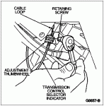
Manual Lever Position (MLPS); also called Transmission Range (TR) Sensor, Adjustment Info in a 92; Located on driver's side of transmission
Source: by Richard C (Bigric, Money Pit)
put it in neutral, loosen the bolts, and line up the marks.

many more MLPS info LINKS in my broncolinks.com site, under Electrical, Sensors
Check all brake light bulbs; regular 1/4 panel mounted and high mounted;
Brake Shift Interlock; These vehicles are equipped with a Brake/Shifter interlock for safety. This system requires the driver to hold the brake depressed before the shift lever can be moved from the Park position. There is an actuator (solenoid) on the left side of the steering column under the dash that disengages the shifter lock when the brake is depressed. In the event this system malfunctions, the shift lever may be stuck in the Park position. One cause of this complaint may be due to a faulty brake switch circuit. If you experience this complaint always check for blown fuses and brake light switch operation before proceeding with other work."
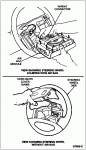
Brake Shift Interlock Overview & Location in Parts Break-Out Diagram in 92-96
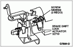
Brake Shift Lock Actuator
Removal
Remove steering column. Refer to Section 11-04.
Unclip wire terminal from brake shift lock actuator.
Remove insert plate and brake shift lock actuator by removing two screws.

Pry off clip.
Installation
NOTE: The clip that retains the brake shift lock actuator to the insert plate should not be replaced for service. The clip's sole purpose is an assembly aid for the assembly plant.
Position insert plate/brake shift lock actuator assembly to the steering column and tighten the screws.
Install the steering column. Refer to Section 11-04.
==========
Steering Column, F-150, F-250, F-350, Bronco and F-Super Duty Chassis Cab
Removal
NOTE: Make sure front wheels (1007) are in the straight-ahead position.
NOTE: All components of the steering column are assembled with fasteners. They are designed with a thread locking system to prevent loosening due to vibrations associated with normal vehicle operation.
Disconnect battery ground cable (14301).
Remove steering wheel (3600) as described in this section.
Remove right and left lower mouldings from instrument panel by pulling up and snapping out of retainers if so equipped. On right lower moulding a ***** will also have to be removed in order to remove moulding from instrument panel.
Remove instrument cluster mask (10890).
Remove air bag sliding contact (14A664) as described in this section.
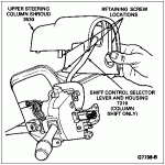
Remove steering column release lever (3D544) by unscrewing it from steering column.
Rotate ignition switch lock cylinder (11582) to RUN position. Using a 1/8-inch drift, depress retaining pin of the ignition switch lock cylinder through access hole in lower steering column shroud (3530) and remove ignition switch lock cylinder.
NOTE: For vehicles with an E4OD transmission (7003), a protective cover (such as a rag) must be placed between the gearshift lever (7210) and steering column shroud opening during steering column shroud removal. This will prevent damage to the shrink wrap on the gearshift lever.
Remove four retaining screws from lower steering column shroud and remove upper shroud from column.

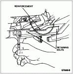
Remove six instrument panel reinforcement brace retaining bolts (if equipped). Remove reinforcement

Disconnect PRND21 cable from steering actuator housing (3F723) by removing one *****.
Disconnect PRND21 cable loop from shift selector hook.

Remove two retaining screws and two electrical connectors from switch. Remove multi-function switch (13K359) from steering column.
Remove pinch bolt from steering shaft flex coupling.
Disconnect shift cable from selector lever pivot.
Remove shift cable from steering column lower mounting bracket by pushing tab on cable in and sliding cable off bracket.
Disconnect ignition switch (11572) by loosening bolt and removing connector. The bolt is part of connector and can not be removed.
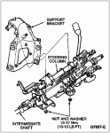
While supporting steering column, remove four retaining nuts.
Disconnect collapsible intermediate shaft from U-joint at lower end of steering column.
Remove steering column from vehicle.

Installation
Align steering column lower universal joint to lower shaft. Install one bolt and tighten to 41-57 Nm (30-42 lb-ft).
Support steering column to column support bracket. Install four retaining nuts and tighten to 13-17 Nm (10-13 lb-ft).
Install shift cable on transmission shift cable bracket (7B229).
Snap shift cable onto shift selector pivot ball.
Connect two multi-function switch electrical connectors. Position multi-function switch and install two retaining screws. Tighten to 2-3 Nm (18-27 lb-in).
Connect all electrical connectors.
Attach PRND21 cable loop on shift selector hook, and install steering column lower mounting bracket to steering actuator housing. Install retaining ***** and tighten to 7-11 Nm (62-97 lb-in).
Install instrument panel reinforcement brace and secure with five retaining bolts. Tighten to 13-19 Nm (10-14 lb-ft).
Install upper and lower steering column shrouds.
Install instrument cluster mask.
Snap right and left lower instrument panel mouldings into place. On right lower moulding a ***** will also have to be installed.
Install ignition switch lock cylinder as described in this section.
Install steering column release lever onto steering column.
Install air bag sliding contact screws, if so equipped. Tighten to 2-3 Nm (18-27 lb-in).
Install steering wheel onto column shaft. Install a new bolt and tighten to 31-45 Nm (23-33 lb-ft).
On vehicles equipped with an air bag, position air bag module to steering wheel. Install four retaining nuts. Tighten to 4-6 Nm (35-53 lb-in).
On vehicles not equipped with an air bag, position steering wheel pad horn switch (13A805) to steering wheel and snap into place.
NOTE: When the battery has been disconnected and reconnected, some abnormal drive symptoms may occur while the powertrain control module (PCM) (12A650) (PCM) relearns its adaptive strategy. The vehicle may need to be driven 16 km (10 miles) or more for the powertrain control module to relearn the strategy.
Connect battery ground cable and air bag backup power supply, if so equipped.
Verify air bag warning indicator.
Steering Wheel with Air Bag
CAUTION: Do not remove the steering column, steering wheel (3600), steering wheel pad horn switch (13A805) and air bag module as an assembly from the vehicle unless the column is locked to prevent rotation. Lower end of steering shaft should be wired to prevent the steering wheel from being rotated.
SPECIAL SERVICE TOOL(S) REQUIRED Description Tool Number
Differential Bearing Cone Remover/Replacer T77F-4220-B1
Removal
Center front wheels (1007) to the straight-ahead position.
WARNING: THE BACKUP POWER SUPPLY MUST BE DISCHARGED BEFORE ANY AIR BAG COMPONENT IS SERVICED.
Disconnect battery to starter relay cable (14300) for at least one minute to let the air bag backup power supply discharge. Refer to Section 14-00.Remove four air bag module retaining nuts from air bag module on back side of steering wheel, and lift module away from steering wheel.
Disconnect air bag wire harness connector, and remove module from steering wheel.
Disconnect horn/speed control wire harness connector in steering wheel.
Remove steering wheel retaining bolt.
Install Differential Bearing Cone Remover/Replacer T77F-4220-B1 and remove steering wheel. Route contact assembly wire harnesses through steering wheel as steering wheel is lifted off shaft.
Installation
Make sure the vehicle's front wheels are in the straight-ahead position.
Route air bag sliding contact wire harnesses through steering wheel opening at the 3 o'clock position. Position steering wheel on steering shaft so the alignment marks are aligned. Be sure air bag contact wire is not pinched.
CAUTION: Make sure wiring does not get trapped between steering wheel and air bag sliding contact (14A664).
Install new steering wheel retaining bolt and tighten to 31-45 Nm (23-33 lb-ft).
Connect horn/speed control wire harness to contact wire harness, and snap connector onto steering wheel clip.
Connect air bag wire harness from air bag sliding contact to air bag module and install module to steering wheel. Tighten module retaining nuts to 4-6 Nm (35-53 lb-in).
NOTE: When the battery has been disconnected and reconnected, some abnormal driving symptoms may occur while the powertrain control module (PCM) (12A650) (PCM) relearns its adaptive strategy. The vehicle may need to be driven 16 km (10 miles) or more for the powertrain control module to relearn the strategy.
Connect battery to starter relay cable. Verify air bag warning indicator.
Steering Wheel