95 bronco with bad ignition cylinder tamper switch

Disclaimer: Links on this page pointing to Amazon, eBay and other sites may include affiliate code. If you click them and make a purchase, we may earn a small commission.

widetrackman

New member
Joined
Oct 10, 2015
Messages
4
Reaction score
0
I have been told to eliminate the tamper sw which is a 163 ohm resistor is to put in a resistor as close as possible to 163 ohm, in my case 150 ohm. I am confused as where to put it. The tamper sw at the cylinder has a black/white dash wire going down the col. in a yellow shield. I have been told to put the resistor between the the dark green/white and ground but cant find where, so I cut the black/dash white wire coming from ign. tamper sw, inserted the resistor on the lower portion of bk/w wire and the other side of the resistor to a ground. Still no crank. I think I need to find the DG/W wire. BTW all the other devices in the starting circuit are ok
 

miesk5

96 Bronco 5.0
Staff member
Moderator
Joined
Oct 18, 2005
Messages
9,071
Reaction score
1,019
Location
Floating in the Pacific
Yo widetrackman,
Welcome to our Bronco site!

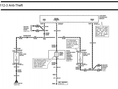
My friend RLA advised "The Ignition Cylinder Tamper Sensor uses a Dark Green/White wire, goes to pin 10 on the Anti-theft Control Module, and a Black/Light Blue wire that goes to ground. The Ignition Cylinder Tamper Sensor should have a resistance between 145 and 175 ohms. Anything outside that range will disable the starter circuit. In theory this means you could wire in a resistor in that range to get around your wonky sensor.
1674132896331.png

The manual states to measure the sensor resistance at Pins 10 and 26 on the anti-theft module. Pin 10 is the Dark Green/White wire. Pin 26 is ground. In theory using any ground reference should work. If you get 0 ohms you have an issue that is triggering the no start problem.

The wires and connector C219 are common with the horn and speed control circuits.
View attachment 198910
 
OP
OP
W

widetrackman

New member
Joined
Oct 10, 2015
Messages
4
Reaction score
0
Yo widetrackman,
Welcome to our Bronco site!

My friend RLA advised "The Ignition Cylinder Tamper Sensor uses a Dark Green/White wire, goes to pin 10 on the Anti-theft Control Module, and a Black/Light Blue wire that goes to ground. The Ignition Cylinder Tamper Sensor should have a resistance between 145 and 175 ohms. Anything outside that range will disable the starter circuit. In theory this means you could wire in a resistor in that range to get around your wonky sensor.
View attachment 30870

The manual states to measure the sensor resistance at Pins 10 and 26 on the anti-theft module. Pin 10 is the Dark Green/White wire. Pin 26 is ground. In theory using any ground reference should work. If you get 0 ohms you have an issue that is triggering the no start problem.

The wires and connector C219 are common with the horn and speed control circuits.
View attachment 198910
The tamper sw was deterioated and cracked, its never been stolen as I am original owner. The only place I have see the DG/W is coming out of the module harness plug (pin 10). So do I cut the DG/W wire back from the plug and install the 150 ohm resistor and then cut the black/? wire coming from the tamper sw going down the column and run it to a ground? I knew about the DG/W wire and a ground but have never been told exactly where or how to wire it.
 
Last edited:

Tiha

Well-known member
Staff member
Moderator
Joined
Jul 22, 2020
Messages
986
Reaction score
1,022
Location
Midwest
remote start bypasses usually have that information, I can try to look it up later. But yes I read that as hook the resistor between the DG/w wire and Black/lb

Back before we had all this fancy info we used to take a good key, grind it down till there was just the resister left, then glue it to the sensor under the steering column cover.
 
OP
OP
W

widetrackman

New member
Joined
Oct 10, 2015
Messages
4
Reaction score
0
remote start bypasses usually have that information, I can try to look it up later. But yes I read that as hook the resistor between the DG/w wire and Black/lb

Back before we had all this fancy info we used to take a good key, grind it down till there was just the resister left, then glue it to the sensor under the steering column cover.
Well I guess I am thick headed. What I still dont understand is actually where I make the connections with the 150 ohm resistor and a ground. Is the 150 resistor spliced in at the DG/W wire coming out of the plug at the module. Where is the ground made, is it made by grounding the BK/ purple (dash) wire coming from tamper sensor? where is the Black/LB. As you can tell wiring aint my fortay!!
 
Last edited:

Tiha

Well-known member
Staff member
Moderator
Joined
Jul 22, 2020
Messages
986
Reaction score
1,022
Location
Midwest
Correct, kind of.

If you look at the wiring diagram above, there is a dashed line around the ignition cylinder tamper sensor.
that sensor should be mounted or glued to the ignition switch so it is close enough to sense the key.

the wires going into and out of this sensor are supposed to be Dark Green with white stripe and Black with light blue stripe according to the wiring diagram.

So you cut the DG/w wire, it goes to one side of the resistor. Then you cut the B/lb wire and it goes to the other side of the resistor.

You can clip the wires right at the sensor, or farther down the column, but need to make sure they are coming from the column main harness end, and not coming from the sensor.

If you are doing it at the anti theft module, then you connect the DG/W wire coming out of the module to one side of the resistor and the other side of the resistor can just go to chassis ground anywhere. You can make your own.

With remote start they attache a relay, so when the remote start powers up it engages a relay that will have that resistance value. So the ECM sees that value while cranking.
Was going to post some diagrams but they would actually make it more confusing.
 
OP
OP
W

widetrackman

New member
Joined
Oct 10, 2015
Messages
4
Reaction score
0
Correct, kind of.

If you look at the wiring diagram above, there is a dashed line around the ignition cylinder tamper sensor.
that sensor should be mounted or glued to the ignition switch so it is close enough to sense the key.

the wires going into and out of this sensor are supposed to be Dark Green with white stripe and Black with light blue stripe according to the wiring diagram.

So you cut the DG/w wire, it goes to one side of the resistor. Then you cut the B/lb wire and it goes to the other side of the resistor.

You can clip the wires right at the sensor, or farther down the column, but need to make sure they are coming from the column main harness end, and not coming from the sensor.

If you are doing it at the anti theft module, then you connect the DG/W wire coming out of the module to one side of the resistor and the other side of the resistor can just go to chassis ground anywhere. You can make your own.

With remote start they attache a relay, so when the remote start powers up it engages a relay that will have that resistance value. So the ECM sees that value while cranking.
Was going to post some diagrams but they would actually make it more confusing.
Thanks I will try this when I get Home.
 

Members online

Latest posts

Forum statistics

Threads
22,516
Messages
135,945
Members
25,119
Latest member
Sgariffo
Top