Well I think we've narrowed down the problem. I just don't know how to fix it. I ran both of the "Short to ground" test as you explained and I get nothing. Not as in 0 resistance, but nothing at all. I verified that my meter was working so that's not the problem. So now what?
You are using an out of date browser. It may not display this or other websites correctly.
You should upgrade or use an alternative browser.
You should upgrade or use an alternative browser.
88 Bronco 5.0 surges when RPMs go over 2000
- Thread starter Jbford
- Start date
Disclaimer: Links on this page pointing to Amazon, eBay and other sites may include affiliate code. If you click them and make a purchase, we may earn a small commission.
Yo J,
"but nothing at all" appears to be an open circuit.
Guessing a wire is an intermittent open, then moving or being moved to being an intermittent short.
A helper can man the meter while you poke harnesses such as at:
self test connector to EEC
to instrument panel
"but nothing at all" appears to be an open circuit.
Guessing a wire is an intermittent open, then moving or being moved to being an intermittent short.
A helper can man the meter while you poke harnesses such as at:
self test connector to EEC
to instrument panel
Attachments
Last edited:
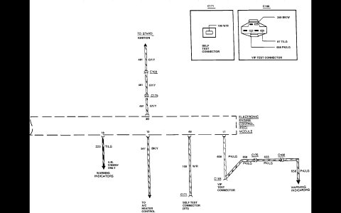
The only thing I've found is that there is an in-line diode just before the plug for the Idle Air Control Valve and with KOEO I'm measuring 12v in and 0.2v out. I'm reading, and have been told, I should have 5v out because this is part of the 5v Reference Circuit. I can't find a replacement diode so I made a trip to Pull-a-part and found a complete harness in a 1989 F150 with the 5.0. I'm just not sure it would match up???? Or am I way off target?
I have not run into the diode before that I remember, but I do know this. Diodes do not regulate voltage. They stop flow.The only thing I've found is that there is an in-line diode just before the plug for the Idle Air Control Valve and with KOEO I'm measuring 12v in and 0.2v out. I'm reading, and have been told, I should have 5v out because this is part of the 5v Reference Circuit. I can't find a replacement diode so I made a trip to Pull-a-part and found a complete harness in a 1989 F150 with the 5.0. I'm just not sure it would match up???? Or am I way off target?
Voltage will only flow one direction through a diode, Like a check ball.
Like and LED (Light emitting diode) polarity matters.
Another thing I know if that is you have 12v and it is supposed to be 5v, that there is a problem someplace else.
From the first page.
That voltage should be greater than 10.5 volts.
looks like the diode is in parallel with the solenoid, or IAC motor plug. So it actually tests good according to the readings you just posted.
Yo J,Wouldn't the diode be at least part of the problem if I'm only getting 0.2v out of it?
Suggest you just do the tests I posted in post #2.
Here they are;

Yo J,
See EEC IV PIN LEGEND to see Pin/Component, etc differences @
See EEC IV PIN LEGEND to see Pin/Component, etc differences @
Truck Computer Pin outs
4x4.forensick.net
Yo David,Can I contact Administration?
It is about advertisement on your website.
Thank.
Member Shaggy is the site owner
I and others are Moderators.
Where is the adverisement?
Last edited:
So it's been a while but I finally got a complete engine and engine bay wiring harness from an 88 Bronco 5.0 and replaced my old one. Right off the bat I now have a working CEL and it sure seems to be running much better. I can even drive it!!!
But, now that I can pull codes, I did. And here's what I got; 13, 14, 34, 63, and 67. Where do I start?
But, now that I can pull codes, I did. And here's what I got; 13, 14, 34, 63, and 67. Where do I start?
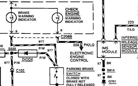
DTC 34 - EGR voltage above closed limitSo it's been a while but I finally got a complete engine and engine bay wiring harness from an 88 Bronco 5.0 and replaced my old one. Right off the bat I now have a working CEL and it sure seems to be running much better. I can even drive it!!!
DTC 13 is Cannot control RPM during ER Self-Test low RPM check. possible causes are:
IAC did not respond properly:
Idle Air Control (IAC) Sludge; Poor Idle TSB 91-25-07 for 85-92 Bronco & F Series & many others; "...Hard cold starts, hesitation and stalls on initial start-up or during idle or decel may be caused by sludge in the throttle body and/or idle by-pass valve. Sludge deposits or oil film on the throttle body bore and plate or the idle air by-pass valve may cause one or more of the following conditions. Hard Cold Start, Stall On Initial Start-Up, Stall During Idle, Stall During Decel, Rough Idle, Rolling Idle, Hesitation During Acceleration. A new idle air by-pass service kit (F2PZ-9F939-A) is now available for service use to correct sludge contamination concerns of the throttle bore and plate only. It eliminates the need to clean the majority of past model throttle body applications. Cleaning is not required on sludge tolerant throttle body designs released for 1991 and newer model years..."
Source: by Ford
Suspect IAC; Removal & Cleaning in a 93 5.8 by Bobby (blue) at 1993 Ford Bronco misc pictures, videos, and sounds | SuperMotors.net
...in Key On Engine Off (KOEO) or Engine Running (KOER) Self-Tests; indicates that the EGR valve may not be fully seated in the closed position; or the EVP sensor voltage is greater than the closed limit voltage of 0.67 volt. Because of the preload on the installed EVP sensor, it is very difficult to determine whether the EGR valve is seated or the EVP sensor is in contact with the EGR valve stem.
•Faulty Vacuum system - See my Vacuum leak test in post #11 incl some jowens HVAC Control Panel pics/info @ Help with dtc codes and idle
One way to do a quick check is to grab a vacuum gauge. Some parts stores will loan you a gauge with refundable deposit.
The vacuum gauge should read between 15 and 22 in-Hg depending upon the engine condition and the altitude at which the test is performed. SUBTRACT ONE INCH FROM THE SPECIFIED READING FOR EVERY 1,000 FEET OF ELEVATION ABOVE SEA LEVEL.
The reading should be quite steady. .
When engine is rapidly accelerated (dotted needle), needle will drop to a low (not to zero) reading. When throttle is suddenly released, the needle will snap back up to a higher than normal figure.
When vacuum leaks are indicated, search out and correct the condition. Excess air leaking into the system will upset the fuel mixture and cause conditions such as rough idle, missing on acceleration, or burned valves. If the leak exists in an accessory unit, such as the power brake, the unit will not function correctly. Or Air Conditioning when in MAX mode may switch to Defrost.
•Damaged EVP sensor
•Corroded or dirty connector
•Damaged EGR valve
•Broken wire in harness
•Grounded harness
•Damaged EEC IV
- Failed sensor, carbon between EGR pintle valve and seat holding the valve off its seat.
Remove the EGR valve and clean it with carbon remover and a brush if necessary
Prior to re-installing see if you can **** air through the ****** side of the EGR by mouth.
●
EGR Valve Position (EVP) Sensor Testing @


DTC 53
TPS circuit above maximum 4.5 volts.
CM TPS circuit has intermittently failed above maximum 4.5 volts.
Test @

63 KOEO TPS circuit below minimum 0.6 volts.
CM TPS circuit has intermittently failed below minimum 0.6 volts.
http://redirect.viglink.com/?format=go&jsonp=vglnk_150315415873115&key=6ed47b392b9edfe394b9e89b72717104&libId=j6jf4ccs01000bgv000MAc63egba4&loc=http://www.fullsizebronco.com/forum/21-noobie-bronco-tech-questions-flame-free-zone/172898-code-13-help.html&v=1&out=http://www.superford.org/registry/vehicles/detail.php?id=3982&s=17193#content&ref=https://www.google.com/&title=code 13 help - Ford Bronco Forum&txt=Removal & Cleaning in a 93 5.8 <br> Source: by Bobby (blue) at SuperMotors.net
Yo J,But, now that I can pull codes, I did. And here's what I got; , 14, 34, 63, and 67. Where do I start?
13, 14, 34, 63, and 67.
Yo
DTC 67 MLPS Test by @Mikey350 @ http://www.fullsizebronco.com/forum/7-1980-96-bronco-tech/405778-very-high-idle-pulled-codes.html
DTC 67 & DTC 634; E4OD Nagging Neutral Nonsense & Pinpoint Test, Manual Lever Position (MLPS) also called Transmission Range (TR) Sensor. "...One of the most-difficult problems to diagnose on a Ford car or truck is a sudden neutral condition while the vehicle is cruising in 4th gear. Now this can have a number of causes, depending on which transmission is in the car or truck, but the cause we are going to discuss here is that #(~! *&A% Manual Lever Position Sensor – that’s right, the old MLPS. This sensor is responsible for more malfunctions than any other sensor in the system, and the kicker is that it seldom stores a code 67 or 634. Actually there is a standing joke in our industry that says, “You got a problem with a Ford, change the MLPS; it fixes everything,” which ain’t that funny because it’s not that far from the truth. Some of the problems the MLPS can cause are wrong gear starts, TCC hunting, no 4th gear, engine stalling, high or erratic line pressure and the problem that this article is about – a sudden neutral condition. Whether the MLPS is attached to an E4OD, AXODE, AODE or CD4E, the operating characteristics are the same. What that means is the MLPS is classified as a step-down resistor. The MLPS is supplied 5 volts from the computer as a reference voltage, and as the shift lever is moved from park toward manual low, the voltage in each gear-shift position will decrease as shown in Figure 1. The MLPS also can be checked for correct resistance, also shown in Figure 1. This way, if the resistance checked good on the bench but the voltage does not check good in the vehicle, you know there must be a wiring or ground problem. I know what you are thinking: You replace the MLPS on every job you do, so why should you check the resistance on a new part? Well, that’s fine, but one thing has become very clear lately: NEW DOES NOT MEAN GOOD! Now, let’s get to the meat of the problem. As you can see in Figure 1, the voltage in the drive/overdrive position can be 1.88 to 2.30 volts. The O.D. Cancel button, on those vehicles equipped with one, has no effect on the voltage seen in the drive position, nor does it matter whether the vehicle has a gas or diesel engine. This would be the voltage seen in the D or D position if it were available on the scan-tool screen in the data mode. Unfortunately, this information is not always available, and this “glitch” may occur faster than the scan-tool’s update capability so the voltage jump would be missed. Therefore, a digital multimeter must be used to monitor this voltage. This is of the utmost importance in diagnosing the sudden-neutral condition. This voltage should be monitored when the neutral condition occurs by placing the multimeter’s positive lead to computer terminal 30 if it is an EEC-IV system, as illustrated in Figure 2, or to terminal 64 if it is an EEC-V system. This wire is light blue/yellow on all applications except vehicles with the CD4E. On these the signal wire is red/black. Now, here is where this gets a little involved. The negative lead of the multimeter should be placed at the MLPS signal-return ground terminal at the MLPS. The reason is that the ground circuit for the MLPS can be shared by as many as FIVE other sensors, as seen in the wiring diagram in Figure 2. This means that there are factory splices in this ground circuit. If you check this ground at computer terminal 46 for the EEC- IV or computer terminal 91 for the EEC-V, the ground may check good but could be bad at the MLPS if there is a problem on the MLPS side of the splice, as also can be seen in the wiring diagram in Figure 2. The ground-circuit wire for 1989-90 F- and E-series trucks is black/white; all other vehicles use a gray/red ground wire except for CD4E applications, on which the ground wire is black/blue. Once the multimeter is connected to these circuits, as seen in Figure 3, place the meter where it can be seen while driving. When the transmission suddenly neutrals, be sure to have someone observe the multimeter, or use the meter’s MIN/MAX feature to record the highest and lowest voltage readings that occurred in the circuit. If the voltage jumps toward 3 volts as shown in Figure 3, and at that very moment the transmission neutrals, either the MLPS is faulty or the MLPS ground circuit is poor. Under normal conditions, this voltage reading SHOULD NOT CHANGE! When the voltage jumps toward 3 volts, this indicates a neutral-shift- lever position to the processor. This confuses the computer’s logic system, and therefore the computer is unable to fire the shift solenoids correctly (I think), and – BAM – you have a sudden-neutral condition. Why does the voltage jump because of a poor ground? The poorer the ground, the higher the resistance will be in that ground circuit. The higher resistance will cause the voltage in the overdrive or drive position to rise toward the 5-volt reference voltage, much like putting a bend in a garden hose would raise the pressure in the hose behind the bend. Ground- circuit integrity can be verified by placing the positive multimeter lead to the MLPS ground terminal at the MLPS and the negative multimeter lead to the negative battery post, as seen in Figure 4. With the multimeter set to DC volts and the engine running, the maximum voltage should be 0.1 volt. If more than 0.1 volt is seen on this ground circuit, it is NOT a good ground. In order to correct this condition, cut the ground wire close to the MLPS, attach it to a known good ground and recheck as previously described. Two things must be remembered here. One is that the return electricity will seek the path of least resistance. This path MUST be the ground circuit, NOT your multimeter. That’s why you should see a maximum of 0.1 volt on any 5-volt-reference ground circuit; 0.3 is acceptable on a 12-volt-reference voltage supply. The second thing to remember is that most electrical- fault phone calls I receive on the ATSG helpline are ground-related problems, so be sure to use the voltage-drop method of checking grounds as described. It may help to prevent you from falling into this trap..."
by Pete L
transonline site is gone, but was able to save Figures 1 & 2;
Attached Thumbnails
Similar threads
- Replies
- 54
- Views
- 13K
- Replies
- 16
- Views
- 4K