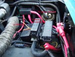
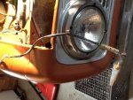
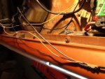
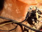
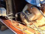
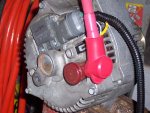
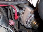
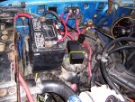
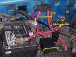
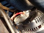
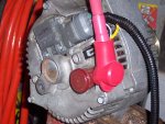
This picture is taken towards the firewall, you can see the yellow wire which goes to the regulator and the heavy black one which goes to the connector plug. They both split off from the fuseable link which attaches to the start solenoid.
Do you mean I should be able to just cut off the small yellow one running to the solenoid and cap it?
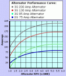
The alt I got was from quality power it's 100 amp they said just run a #6 wire from it to the solenoid.
Ken
First off, a number 6 wire is a little light, I wouldn't do any less than a number 4 with a 100 amp alternaator. A number 6 will work but only because you are not drawing the full load of the alternator. If you add more load like Off Road lights, sound system, etc. a number 6 wire will start to get hot and cause a voltage drop in the systemthat you don't need. If you had put in a 130 amp alternator then # 2 is best. In other words, 6 will work but 4 is electrically better.
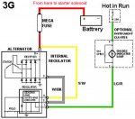
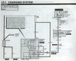
With your alternator, (just as in the above diagram), I recommend a #4 from the alternator charge terminalto a 125 amp Mega fuse. From the fuse to the battery #4, from the fuse to the battery a #4, from the battery to the start solenoid, whatever was originally there (standard battery cable).
That gets the start and charge system functioning properly and safely. The next thing is to reestablish connection to the rest of your electrical system. A secondary objective is to get rid of the old voltage regulator and wires thar originlly went to the old alternator/generator.
If you had an Ampmeter on the dash, it will no longer function. From my experience, most of them didn't work any way so no big loss, a voltage meter is a better indication of what's going on with your alternator anyway.
I'm adding a picture of the 3G alternator harness that I expect you are using with some comments on the picture.

The yellow wire is the voltage sense wire, It lets the alternator know what to do in regulating the voltage output. If it is connected to the point of distribution for the electrical system it will do a better job of controling the voltage output level. Though connecting it at the charge post lets the regulator know what level the alternator is putting out, it is more accurate if connected further down the line, (if you dont understand that, I don't want to waste time inputting the defense of that statement in this post, just believe me, it is true).
The white one obviously goes to the alternator field connector.
The Green with red stripe connects to the green with red stripe wire in your old connector from the dash. It should be one of the wires going to the connector thar is unplugged. Cut it and connect it to the green with red stripe wire going to the alternator harness.
To make the connection to the voltage distribution point I need to see where those two black wires go that are in your picture. I assume one goes to the fuseable link.
Waiting for your input and perhaps a coupe more pictures. If I were there we would have this done in about 10 minutes. The extreem tunnel vision I have under your hood makes this a little difficult and I'm not sure if what I have said so far is confusing or makes ant sense to you.
At this point, I would need to see where the black wires in your picture go.

>-

