Hey there Iyo
Welcome to the zone!
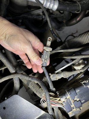
Wires first. The black wire in the pict goes to the capacitor. (The silver cylinder directly behind the connector in the pict.) If you look at the bottom of it, you will see the broken wire. Its there to absorb EMI (electrical noise) from the ign coil. It needs to be there.
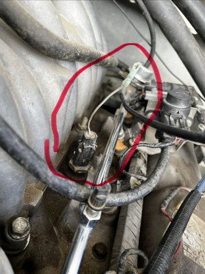
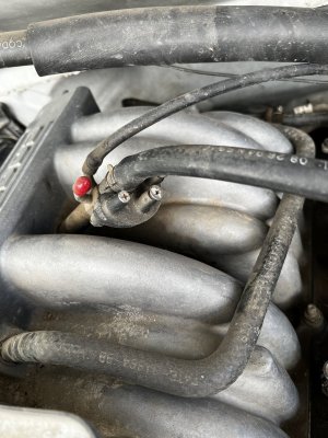
There should be a hose connected to the port on that solenoid for sure.
It looks like the vac solenoid for egr.
That poor truck looks like its been the victim of an emission controls bandit,
Some people believe that removing all of the pollution controls will make it run better, in most cases, the opposite is true. Those egr valves and thermactor pumps work with the engine controls. Its an age old story.
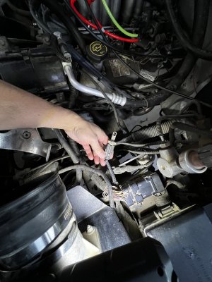
Looks like the wiring took a hit as well.
Do you have to meet air care or some kind of emissions compliance to register? If it all has to work, I would recommend an engine wiring harness and vacuum harness from a
95f-150/Bronco and start fresh.
Depends on how far you want to go.
Heres a pict of the vac routing sticker that should be on the rad support or underside of the hood.
View attachment 32882
Hope this helps
Cheers!


 are being good to all.
 send-off yesterday.