Solved! (Possibly) - Add relays to current window wiring

Disclaimer: Links on this page pointing to Amazon, eBay and other sites may include affiliate code. If you click them and make a purchase, we may earn a small commission.

cowboyup351

New member
Joined
Aug 18, 2011
Messages
20
Reaction score
1
I own a 1986 FS Ford Bronco and it has the original style window and door lock switches. Both are 5 pin switches. From what I understand, all the power runs through those switches to the motors and it wreaks havoc on them. My question is:

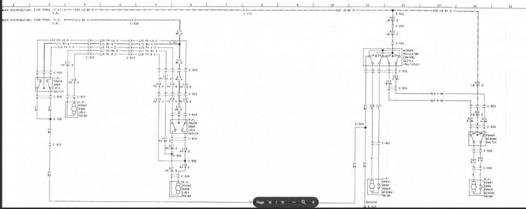
Can I rewire the current setup (I have attached the (hopefully correct) schematics) utilizing the original external hardware (OE door locks and window switches), but rewiring the internal setup, utilizing 5 pin relays, so the electronics aren't so taxed.

If that's possible, could someone be so kind as to draw out how to do that, like I am a 5th grader (who knows how to solder)?

I have rewired, with new wiring, the locks a windows a couple of times (as I have owned this truck for 25+ years) and the electronics wear out quickly. The window and door lock motors all bench test well, but once installed, they periodically fail. I have tested the wiring and installed thicker ground wires, but to no avail. Thus the reason I would like to possibly try a new approach.

Is this something I can even do, or am I just crazy (which is very possible)?

TIA
Windows and Locks.JPG
 

Tiha

Well-known member
Staff member
Moderator
Joined
Jul 22, 2020
Messages
986
Reaction score
1,022
Location
Midwest
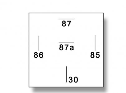
Standard 5 pin relays are all numbered the same, layout is the same. As pictured below.

For what you want to do, you will need 2 for each window motor and 2 for each door lock motor.

Terminal 30, on every relay will be Battery supply 12V. Fused is not a bad idea.
Terminal 87A is normally closed and will always need to be grounded.
Terminal 87 is normally open and needs to go to the motor you want to control.
terminal 86 controls the relay and always needs to be grounded.
Terminal 85 controls the relay and will come from the switch.

Using the diagram you posted. We will take the example of the RF power window motor located in the lower RH corner of the diagram.

Wire 333, yellow with red stripe.

Cut that wire.

The control wire side from the switch goes to Terminal 85 on relay.

The load wire side To the motor goes to Terminal 87 on the relay.

Repeat for each wire.
Red with yellow stripe (RF window)
Red (LF window)
Yellow (lf window)
Pink (RF door lock)
Pink with black stripe (RF door lock)
Same colors for lf door lock.

Hope that helps.
100-50-diagram.jpg
 
OP
OP
C

cowboyup351

New member
Joined
Aug 18, 2011
Messages
20
Reaction score
1
Standard 5 pin relays are all numbered the same, layout is the same. As pictured below.

For what you want to do, you will need 2 for each window motor and 2 for each door lock motor.

Terminal 30, on every relay will be Battery supply 12V. Fused is not a bad idea.
Terminal 87A is normally closed and will always need to be grounded.
Terminal 87 is normally open and needs to go to the motor you want to control.
terminal 86 controls the relay and always needs to be grounded.
Terminal 85 controls the relay and will come from the switch.

Using the diagram you posted. We will take the example of the RF power window motor located in the lower RH corner of the diagram.

Wire 333, yellow with red stripe.

Cut that wire.

The control wire side from the switch goes to Terminal 85 on relay.

The load wire side To the motor goes to Terminal 87 on the relay.

Repeat for each wire.
Red with yellow stripe (RF window)
Red (LF window)
Yellow (lf window)
Pink (RF door lock)
Pink with black stripe (RF door lock)
Same colors for lf door lock.

Hope that helps.
View attachment 31251
Thank you! I had a feeling it was simple, but I wanted to get someone smarter than me to make certain it would work and would help lighten the load. I really appreciate that
 
OP
OP
C

cowboyup351

New member
Joined
Aug 18, 2011
Messages
20
Reaction score
1
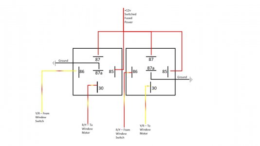
For some reason, that setup didn't work. With a lot more research, I came up with this and it seems to work like a charm (albeit it is opposite of nearly EVERY schematic I came across that shows 30 is power input). Why, who knows... I am guessing magic. But attached is a schematic that seems to work like a charm and the windows go up when I press up and down when I press down. (Also, no idea why I had to swap the Y/R and R/Y wires to opposite relays from switch to motor, but it works.

Maybe someone here could opine a technical explanation for me, if they don't mind.

Hopefully this helps someone in the future.

Bronco Window Relay Schematic.jpg
 

Tiha

Well-known member
Staff member
Moderator
Joined
Jul 22, 2020
Messages
986
Reaction score
1,022
Location
Midwest
The difference is the diagram I used was a Ground to energize, and the setup you ended up using is a Power to energize.

Is that the right wiring diagram? Maybe I need glasses.

The only difference is you ended up putting 12v on pin 85 where as I was grounding it.

Either way, good info. glad you got it working.
 
OP
OP
C

cowboyup351

New member
Joined
Aug 18, 2011
Messages
20
Reaction score
1
The difference is the diagram I used was a Ground to energize, and the setup you ended up using is a Power to energize.

Is that the right wiring diagram? Maybe I need glasses.

The only difference is you ended up putting 12v on pin 85 where as I was grounding it.

Either way, good info. glad you got it working.
Thank you, Tiha. I really appreciate your help. I pulled that schematic from Gary's Garagemahal (https://www.garysgaragemahal.com/wiring-diagrams.html), but it's highly possible I pulled down the incorrect one. Now, on to the door locks, which should be the same/extremely similar setup
 

Members online

No members online now.

Latest posts

Forum statistics

Threads
22,516
Messages
135,945
Members
25,119
Latest member
Sgariffo
Top