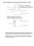
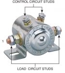
Except for the non-use of industry standard numbering, it is the same. The second diagram shows the contact numbers from the same view as the first picture. They get you started by numbering the first contact in the picture. Counting clockwise the contacts in the picture are !, 2, 3, 4 and are numbered the same in the schematic. Forget anything else in their sample diagram, it is not relative to what youa re doing and is only an example of how the relay could be used. You do not need to mount the fan relay to the body, and I wouldn't use the body for grounding. The numbers in their schematic equate to the following numbers in my schematic: 1 = 30, 2 = 86, 3 = 85, and 4 = 87. Number 3 on your relay should have a ground, (I would run a ground lead fro it to battery ground). I would run a #8 wire From Battery (+) to number 1 via a fuse (a 50A **** fuse should do, you can get that and a holder at some place like Auto Zone). If you are not going to dive right in to the Override circuitry hook the RED lead on the Imperial control to the Fan relay #1 = 30 the same cintact the #8 wire from the fuse hooks.
Be careful when installing the probe so that you don't damage your radiator and put the probe buttons on where they show you. Install it as close to the radiator hose as possible.
As shown in the diagram, you need to find a place to pick up a +12V line that is only hot when the key is on. Ford standard marking for switched +12V is as indicated Red/Lt Grn hooks to the Imperial yellow wire. The imperial BLACK lead can be run to same lug on your Fan Relay as the ground wire, previously installed, (3 = 85).
Your Fan Relay #4 = 87 goes to the fan (+) lead. Your Fan (-) lead goes to the same place you picked up Battery (-). In my truck, I made several battery ground connection blocks. That will make your installation a little cleaner, but worry about cleaning things up after you know the control is working.
Your diode can be installed right on the Fan relay from terminal (4 = 87) to terminal (3 = 85),striped end on terminal (4 = 87).
If you buy any wire for this project, be sure to get automotive grade wire. Standard wire has thicker strands in it and is less flexible and will break easier from flexing.
Attached is the other diagram I promised you.

>-


