So I got the new components installed and tested. As a reminder we were trying to fix this problem....
With the new LED bulbs, my running lights turn on my LEDs at max brightness. This effectively causes an issue where my brake circuit won't make the lights brighter.
I believe This was a result of voltage back feeding into the brake/turn signal circuit wiring. The LEDs on the market have a large tendency to bleed voltage from the running light circuit into the Brake light circuit. This also means that for those of us that have E4OD transmissions, the voltage that is back feeding the running light circuit and causing brake lighting issues will also cause transmission shifting issues because the Voltage will back flow to the BOO wire at the EEC. That connection would end up being energized with a false signal that brakes are activated and disengage the torque converter lockup and may also engage the Coast Clutch Solenoid. This effectively would fight the progress of the engine trying to move the Bronco forward which could result in a overly warm transmission.
The solution to this issue is to isolate the
REAR LED 3157 lights from all the other signal wires. Had Ford done this in the factory they could of added relays or diodes in harness. Since this is a after market install all the work now nneds to be done in the rear of the vehicle.
NOTE: If your wondering why only the rear needs to be isolated Its because the turing signal switch isolates the front lights already.
Supplies:
I choose to use Schotty diodes due to their low voltage drop of only .367v compared to that of a Silicon Diode of ~.7v. Losing almost a whole volt of lighting power isn't good. .3v isn't ideal either but its be best option I could find. During my research I also found out that Load resisters are needed so the cruise control would function properly. The explanation on this wasn't very clear of how or where the cruise control ties into the circuit but not having them results in the Cruise control not working but as I had one Bronco owner explain it, "Voltage is bled off through the filiment of the bulbs to know if the brakes are pressed or not." Thus by installing LED bulbs voltage can't bleed off making the circuit think the brakes are being pressed.
NOTE: The resistors are needed because they provide a path to ground after the brake switch has been released. This helps the transmission and Cruise Control function properly. In some cases if the BOO wire on the EEC 60pin connector has any voltage the EEC can change the timing of the engine cutting power, Hold gears longer then desired(E4OD), and not allow the Torque Converter to lock up(E4OD).
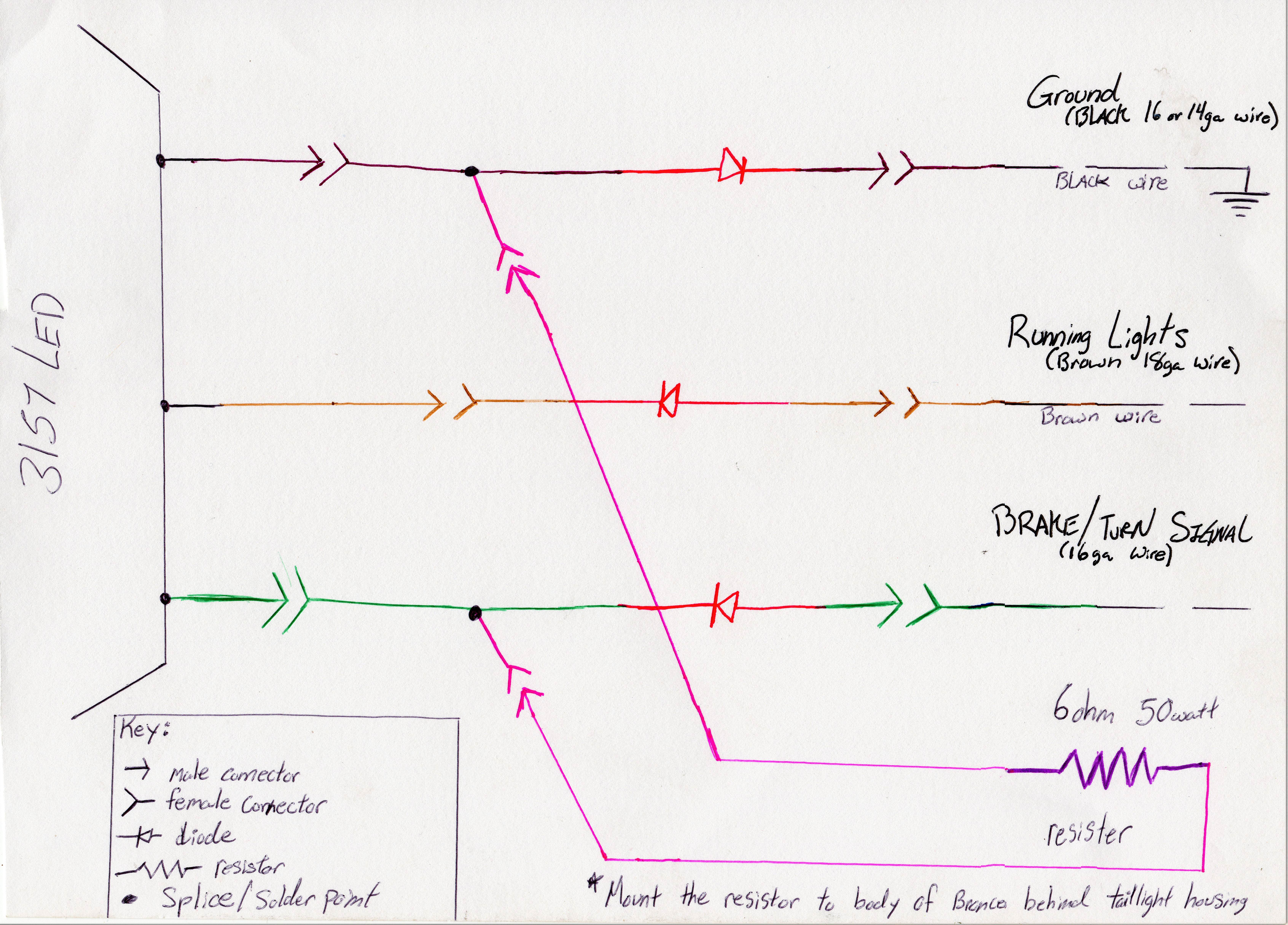
Hear is the wiring diagram that I made to explain what needs to be made to isolate a 3157 LED bulb.
NOTE: (In the photo I used 1 6ohm resistor, I had to update my wiring because I found that a 12ohm worked better.)
The Diodes stop current from flowing backwards in the circuit. Heat shrink tubing is used like crazy to keep dirt and water out of the connections.
*** You must solder the diodes to the wire that you are putting the blue connectors on.
And here is the result of what parts were made:

The result looks messy but is cleaned up with zip ties


At the time of this post I havn't tested the the set-up on a long trip around town but my lights do work correctly now.
I've been runnning this set up in multiple vehicles for 2 years now with no issues.