Dual Battery Setup

Disclaimer: Links on this page pointing to Amazon, eBay and other sites may include affiliate code. If you click them and make a purchase, we may earn a small commission.

MOJIGGA

New member
Joined
Aug 16, 2012
Messages
57
Reaction score
1
I recently hoooked up my dual battery setup, everything seems to work fine, but my gauge inside the truck is only reading about 9 or 10 volts.....this should be 14 correct? i attached a picture of my wiring diagram. can anybody give me pointers of why my gauge only reads 9 or 10 volts?

i have a 95 amp alternator, 160 amp isolator, a yellow top and red top optima. any help is greatly appreciated.

thanks,

Mojigga

 
OP
OP
M

MOJIGGA

New member
Joined
Aug 16, 2012
Messages
57
Reaction score
1
found out, that i was running strictly off the battery. apparently my alternator was not charging them. now i either have them hooked up wrong, or my isolator is not working...

any suggestions?


miesk5

96 Bronco 5.0
Staff member
Moderator
Joined
Oct 18, 2005
Messages
9,071
Reaction score
1,019
Location
Floating in the Pacific
yo  MOJIGGA,

1979 Ford Bronco, Correct?
If so;

Here is the 1979 Ford Bronco Wiring Manual (PARTIAL)by topsig at http://www.supermotors.net/registry/24302/78593

Clicik on each page's image or diagram to enlarge

page 5 shows factory duals depiction

master-gunz005.gif

page 8 shows wiring diagram for duals

master-gunz008.gif

isoldiagram.jpg

he 4WD Systems Intelligent Isolators have been designed to meet all the needs and requirements of a dual battery electrical system in the modern 4WD vehicle. All models feature voltage and load sensing circuitry for switching plus inbuilt surge protection to prevent damage to other electronic equipment in the vehicle. The Heavy Duty model has an additional electronic circuit controller which has auxiliary load sensing to protect the alternator from overloading plus Jump Start capability from the dashboard. All models are simple to install and are water resistant.  Read More

http://www.4wdsystems.com.au/index.php?id=24

Dual Batteries Installation in a 79 F 150 (same as Bronco)

78/79's are easy. They have matching places for batteries. So I have one on each fender well.
The cable is the +12v from the battery to the starter relay (solenoid)

.https://lh6.googleusercontent.com/-dFgd9i7FI5M/TmlaYRO5kyI/AAAAAAAAJsU/HOACko4rm-Y/s912/DSCN4159.JPG

This cable is feeding the isolator going to the auxiliary battery

https://lh3.googleusercontent.com/-TYw5WAxfWZI/TmlaX_wyVJI/AAAAAAAAJsQ/sgd3y-JVE3w/s912/DSCN4160.JPG

This cable is going down to the starter

https://lh5.googleusercontent.com/-8aShN5aTsas/TmlaX0E8KbI/AAAAAAAAJsM/Cr5W7__CPzM/s912/DSCN4161.JPG

This is the +12v from the alternator.

https://lh5.googleusercontent.com/-i0jdjw-wt08/TmlabF8y5BI/AAAAAAAAJsc/WCeClfccOvE/s912/DSCN4163.JPG

The alternator wire goes to the mega fuse and the to the isolator. The factory uses a fusible link in there alternator wiring. I upgraded alternator to a 3g capable of 130 amps so I have a large mega fuse to protect the wiring. It connects to the same pole with the wire that came from the starter relay (solenoid).

https://lh6.googleusercontent.com/-yUrphxd9UUc/Tm1GbvpVqGI/AAAAAAAAJwA/2508Ei-nlB4/s912/DSCN4210.JPG

This cable leaves the isolator and goes to a mega fuse at the auxiliary battery.
https://lh5.googleusercontent.com/-Jn6NNlzILho/Tm1GfrBdeaI/AAAAAAAAJwI/wQvettaIW7c/s912/DSCN4213.JPG

https://lh4.googleusercontent.com/-nynmCwjQ8Jk/Tm1Gj77si7I/AAAAAAAAJwY/Ksg0W1gaUSQ/s912/DSCN4217.JPG

This wire is the auxiliary battery +12v to the mega fuse. I installed a fuse here to protect the cable/truck because of the length of cable and possibilities of something shorting the cable. In my opinion its worth the extra $12.

https://lh3.googleusercontent.com/-4aX66Bh80KQ/Tm1Gmpkky-I/AAAAAAAAJwg/S5hKQvWvg0Y/s912/DSCN4219.JPG

The winch cable is fed from the battery +12v cable on the line side of the mega fuse. This way it takes its power from the auxiliary battery when the engine is not running.
https://lh6.googleusercontent.com/-M2KIo9641RQ/Tm1GksikDEI/AAAAAAAAJwc/BNYU3vvfyZQ/s912/DSCN4218.JPG

better view of everything

https://lh4.googleusercontent.com/-g_rCnocVfAU/Tm1Gil_GcbI/AAAAAAAAJwU/hWzLBvUJBuM/s912/DSCN4216.JPG

From each of the battery negatives I grounded to the same piece of steel on the truck

https://lh3.googleusercontent.com/-eBFWhVqNICY/Tmlaj9kkHCI/AAAAAAAAJs0/2n5T8tCfQg0/s912/DSCN4169.JPG

Here is both frame connections
https://lh3.googleusercontent.com/-_U0piV0AZsI/Tmlafgr7GJI/AAAAAAAAJsw/lyOsvHMuqLA/s912/DSCN4168.JPG

https://lh6.googleusercontent.com/-bwnNnOr3tfY/Tmlak_F2FdI/AAAAAAAAJs4/fzo7gfFJ_NA/s912/DSCN4170.JPG

My old battery negative cable went to the engine block and because the new cables do not I ran a cable from the same piece of steel to the engine block to ground it.
https://lh5.googleusercontent.com/-y3pQfOsYWlo/TmlaoQG2FJI/AAAAAAAAJtA/tryXBpdHMG8/s912/DSCN4172.JPG

All that is left is the control wiring for the isolator. This is very easy. All you need is a +12v source that is hot when the key is in the run position. I used the wire that provided +12v to my reverse lights switch. The reason I chose it is its close and with my transmission conversion it was no longer used.

https://lh3.googleusercontent.com/-s9p_ZN0LmU0/Tm1GfhDIQJI/AAAAAAAAJwM/N1WyszJfp4E/s912/DSCN4214.JPG

The other side you just ground it.
https://lh4.googleusercontent.com/-ofvbWwbzoSA/Tm1GgEWECbI/AAAAAAAAJwQ/K6Uue9RJNIE/s912/DSCN4215.JPG

Now operation of this set up.

When you are driving/truck is running the isolator will close paralleling the to batteries together and charging both batteries at the same time. If you use a heavy accessory such as a winch while the engine is running it will receive the power of both batteries and the alternator will try to keep them charged.

If your engine is off like you trying to winch you dead truck on the trailer. The isolator will open and the auxiliary battery will carry all the load of the winch. The benefit to this is if you get the truck on the trailer and it kills the battery to do it. Now you have got home to where all you tools are and fix your truck. Your starting battery is still good and you can start your truck. Now the isolator will not close until the truck is running or you let the key turn to the run position because the ignition system when the key is turned past the run position to the start position cuts all unnecessary power. Once the engine starts and the key turns back to the run position the isolator will close and charge the dead battery.
 

by 79F150


Dual Batteries Installation Info & pics in a 79
Source: by axaviere (Truck) at SuperMotors.net

Wiring Diagram in a 79
Source: by Chilton

Dual Batteries Disconnect Schematic
Source: by Wells

 
OP
OP
M

MOJIGGA

New member
Joined
Aug 16, 2012
Messages
57
Reaction score
1
Miesk,

im actually hooking up the dual batteries in my 1996 Bronco.

but this is good info.

my alternator wire goes directly to the isolator, and then two (+) cables which go to each battery.

i see in that diagram the alternator wire goes to the main battery and then to the isolator.

if i could figure out how to put a picture in this message i could show you my diagram of how its hooked up.

thanks for the info though,

-Mojigga


miesk5

96 Bronco 5.0
Staff member
Moderator
Joined
Oct 18, 2005
Messages
9,071
Reaction score
1,019
Location
Floating in the Pacific
yo,

ok

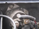
To begin with this is as built;

from

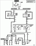
Section 14-00: Battery and Charging System, Service
1996 F-150, F-250, F-350, F-Super Duty and Bronco Workshop Manual
DIAGNOSIS AND TESTING
Electrical Schematics Charging System, Gasoline j6281b.gif


This is by Painless
http://www.painlesswiring.com/Manuals/40102.pdf

It is diff than the 4WD Systems Intelligent Isolator diagram I showed in prev reply

So, if you know the isolator brand, it will help id what diagram to use.

excerpt; "

Connect your winch positive power cable to the main battery. This is to allow the alternator to

power the winch along with the main battery when in mode two (2). Winching in mode two (2)

will hold the auxiliary battery in reserve for jump-starting. This is important if you stall the motor

or turn the key off after winching without allowing the main battery to recharge. Note: It is best

to run the engine 5 to 10 minutes after a winching operation to recharge the main battery.

Connecting the winch to the main battery is opposite from all other dual battery systems. When

using the Cirkit Boss Good Samaritan Dual Battery System you must connect the winch to the main

battery for optimum winch operation.

Stereos and Amplifiers

Connect your car radio and amplifiers to the stock, main, battery. This will allow the system to

turn off with the key. By connecting the stereo in this manner you will make sure that the stereo

will not drain the main battery by being left on accidentally when exiting the vehicle. Always

connect the stereo to the accessory side of the key..."

To post a pic from your PC, look below @

Attach Files

has a paper clip depiction to the left

Max. single file size: 750MB  Click on Choose Files find the pic you want to post...Have to go through this myself since we have an updated forum now/then Add Reply 
 
OP
OP
M

MOJIGGA

New member
Joined
Aug 16, 2012
Messages
57
Reaction score
1
Miesk,

why wouldnt this setup work for me?

do you have any ideas?

wiring diagram for dual batteries.jpg

 
OP
OP
M

MOJIGGA

New member
Joined
Aug 16, 2012
Messages
57
Reaction score
1
Miesk,

i have the Surepower brand.  and it doesn;t call for a ground from the isolator (only has 3 studs, 1 for the alternator, 1 for each battery)

its either the 120amp or 160amp, i can;t remember which.


miesk5

96 Bronco 5.0
Staff member
Moderator
Joined
Oct 18, 2005
Messages
9,071
Reaction score
1,019
Location
Floating in the Pacific
yo M,

ok,

I looked up Sure Power

they say, "Up to 1998 and newer Ford Motorcraft alternator systems having the three wire plug connector. Call Sure Power Industries for a separateset of instructions and modification procedure for the two-plug alternator system that does not have an output bolt. "

Also see http://www.cooperindustries.com/content/dam/public/bussmann/Transportation/Resources/instructions/BUS_CBT_INST_180012q.pdf

See diagram on page 2

For ground; Intake Manifold to Block Strap Location pic in a 96

http://www.supermotors.net/getfile/727560/original/dsc_0505.jpg

by bossind

Also, fyi, "In 1996 Ford publicly recognized the fire hazard caused by the 2G alternator and released TSB 96214. This alternator design caused increased resistance and heat which could damage the wire harness and alternator. A small percentage of vehicles actually caught on fire!

3Galternator02sm.jpg
Fords 3G alternator was a giant leap in technology and quality. The 3G was internally regulated, used two internal cooling fans, sealed bearings, and had a superior battery stud. The 3G’s were more efficient, and produced more amperage at idle than any of its predecessors."

Source: by Ryan M


3G Install Tech http://oldfuelinjection.com/?p=75 by Ryan M


OP
OP
M

MOJIGGA

New member
Joined
Aug 16, 2012
Messages
57
Reaction score
1
Thanks Miesk,

you guys are awesome on this site!

one thing i have noticed in all these diagrams is they never say anything about the selenoid?!

i got wires running from the selenoid all over the place, to the alternator, starter, to the battery...


miesk5

96 Bronco 5.0
Staff member
Moderator
Joined
Oct 18, 2005
Messages
9,071
Reaction score
1,019
Location
Floating in the Pacific
yo M,

yw

Solenoid... The unit mounted on passenger side inner fender near batty is described by Ford as starter relay

The unit atop starter is descr as the solenoid.

===

Here is the relay on my 96 Bronco 5.0 without any changes since new

IMG_0927.JPG

96starterwiring.gif

=

Item Part Number Description 1 N805403 Terminal Nut 2 11390 Starter Solenoid 3 11A171 Seal 4 11130 Drive End Housing 5 N805405 Solenoid ***** (2 Req'd) 6 11001 Starter Motor 7 11135 Bushing 8 11A196 Drive End Housing Seal Ring 9 11005 Starter Motor Armature 10 11A172 Armature ****** Ball 11 11A167 Planet Gear Retainer 12 11K190 Planet Gear 13 11355 Output Shaft 14 11A165 Stationary Gear 15 11036 Pinion ****** Washer 16 N805404 Truarc® E-Ring 17 11067 Drive Lever and Pin 18 11350 Starter Drive 19 11180 Drive End Housing Seal 20 11223 Stop Ring Retainer 21 11222 Starter Drive Stop Ring 22 — Magnet Pole Piece (6 Req'd) (Part of 11075) 23 — Pole Shunt (6 Req'd)
(Part of 11075) 24 — Magnet Retainer (6 Req'd) (Part of 11075) 25 11075 Starter Frame and Magnet 26 11061 Brush Holder 27 11059 Brush Spring 28 — Bushing (Part of 11049) 29 11049 Brush End Plate and Bushing 30 N805406 Brush Plate ***** (2 Req'd) 31 N805428 Through-Bolt (2 Req'd)
j6438a.gif


Attachments

  • IMG_0927.JPG
    IMG_0927.JPG
    102.3 KB · Views: 1
  • 96starterwiring.gif
    96starterwiring.gif
    18.6 KB · Views: 1

Members online

Forum statistics

Threads
22,520
Messages
135,977
Members
25,124
Latest member
Fryman22
Top