4x4 Not Working

Disclaimer: Links on this page pointing to Amazon, eBay and other sites may include affiliate code. If you click them and make a purchase, we may earn a small commission.

chuckles1856

Member
Joined
Aug 3, 2004
Messages
105
Reaction score
8
Greetings,
Don't get to "play" with the Bronco much anymore but recently troubleshooting running rough and discovered the 4x4 is not working. If it's not one thing it's another.

1991 5.8L Ford Bronco XLT with push button 4x4 and manual locking hubs

Symptom: Push the 4x4 button on dash and nothing happens. No click from T-case control module, no light on dash, no sound of the motor engaging the T-case

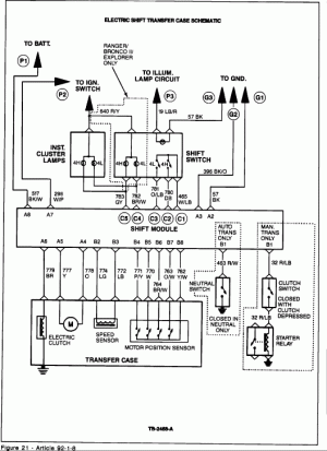
I found this awesome doc outlining troubleshooting.

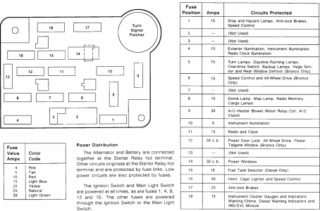
Tried the self test on the T-case control module and got no flashes from the LED. I'm assuming the module is bad at this point but wanted to make sure I covered all basis before I go hunting for a new/reman unit. Like making sure the T-case control module has power and grounded. It appears to be on the same fused circuit as the door locks and they are still working so assuming yes. Just didn't know if there was a good way to check at the module, back probe the wires?

Part of the reason I ask is that the rear power window switch on the dash quit working a while back but I'm still able to roll the window down with the key. Didn't know if the two could be related somehow. I remember long while ago the ignition switch came a part and door locks quit working, the dash lights were coming on randomly I was thinking I had a possessed truck until someone told me to check the ignition switch and found it was falling apart. The ignition switch feels ok when I reach up and feel it on the steering column but I know that doesn't mean a whole lot. <smile>
 
OP
OP
C

chuckles1856

Member
Joined
Aug 3, 2004
Messages
105
Reaction score
8

johnnyreb

Well-known member
Joined
Feb 23, 2021
Messages
2,423
Reaction score
1,069
Location
West Virginia
Thanks Miesk5! Checked the fuse and it's good. That's good info about certain fuses being powered all the time. Looks like the T-case control module is out. I'll start looking for a replacement.
Also you might want to check and ss if their is any in line fuseable links. I didn,t know my 78 had them .I checked the fuses .Then when I started checking the wires. I had a couple.
 

johnnyreb

Well-known member
Joined
Feb 23, 2021
Messages
2,423
Reaction score
1,069
Location
West Virginia
Also you might want to check and ss if their is any in line fuseable links. I didn,t know my 78 had them .I checked the fuses .Then when I started checking the wires. I had a couple.
Check Green Auto Part for NEW OLD PARTS--1-800-543-4959 in Ohio.
 
OP
OP
C

chuckles1856

Member
Joined
Aug 3, 2004
Messages
105
Reaction score
8
Greetings All,

So I finally got to the junkyard and pulled a shift control module. It fixed the problem for a while but now I'm back with no 4x4. And I hear no click from the module when the button is pressed.

This time the module passes the self test. I found some more troubleshooting steps over here I think.


With the key on but engine not running:

1) 5 pin connector
4x4 and Low Range buttons both had continuity DB & W/LB O/LB & W/LB wires

2) At the 8 pin connector:
Neutral Switch had continuity when shifted into neutral R/W wire
Speed sensor ohm'ed out at 321 ohms LG & LB wires
No continuity from any of the Motor Position Sensors wires

When I started the engine I checked the 8 pin connector again in neutral but got nothing from the Neutral Switch sensor. I thought this was strange.

At this point I'm thinking it's the transfer case motor not sending the proper signals back to the module. As the troubleshooting doc says 3 or more open circuits from the motor position sensor means something is wrong with the motor and sensor assembly.

Also, my 8 pin connector is is falling apart. Does anyone know of a place where they sell these replacements? I don't want to have to buy a whole wiring harness. Push comes to shove I could probably yank one at the junk yard but I thought if I could get a new one that would be best.


Thanks in advance for all the help!
 

Tiha

Well-known member
Staff member
Moderator
Joined
Jul 22, 2020
Messages
986
Reaction score
1,022
Location
Midwest
It is funny how often it seems the motor and control module fail at nearly the same time.
So yeah I would grab the motor as well.

Don't know about the replacement plug but if you can grab one from the junk yard and splice it in that works.
I know cutting and splicing is not the best solution but better than a new harness.

If you take your time, use some electrical grease and heat shrink butt connectors. You can put phasic wrap over it and nobody will ever know.
 
OP
OP
C

chuckles1856

Member
Joined
Aug 3, 2004
Messages
105
Reaction score
8
Hey Tiha thanks for the suggestions. I had to do this with the power to tail gate window a while back. Heat shrink tube... best friend to a wire without insulation :)
 
Last edited:
OP
OP
C

chuckles1856

Member
Joined
Aug 3, 2004
Messages
105
Reaction score
8
Ok riddle me this Broncofolks
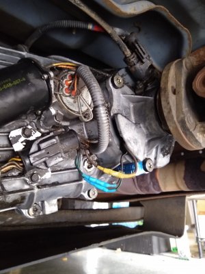
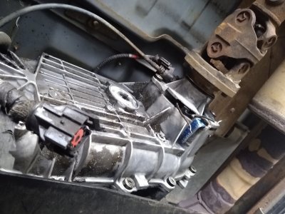
Grabbed a motor from junkyard. Snipped the 3 wires to the speed sensor as is was behind the yoke on the t-case. It ohmed out good.
Swapped it out and checked the continuity at the 8 pin connector. None of the motor position pins had any continuity. Figured it was bad too but plugged it into the shift control module and to my surprise it shifted.
So I swapped back in the old one and it shifted too.

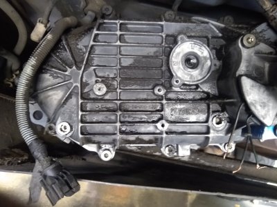
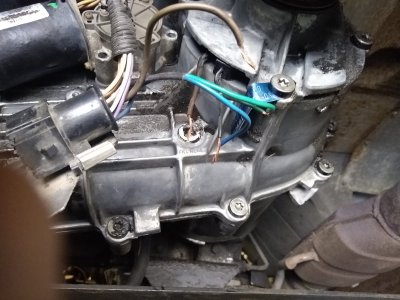
The only thing I noticed was tranny juice in the motor housing and the connector.

In any case I was testing by connecting the positive lead of VOM to the connector pin and the negative lead to ground. This works for the neutral pin.

Any thoughts on why this was not working and the connectivity at the pins isn't working.

I'm super confused.
 

Attachments

  • IMG_20221015_133442983.jpg
    IMG_20221015_133442983.jpg
    230.7 KB · Views: 8
  • IMG_20221015_123130291.jpg
    IMG_20221015_123130291.jpg
    258.1 KB · Views: 8
  • IMG_20221015_123044956.jpg
    IMG_20221015_123044956.jpg
    256 KB · Views: 9
  • IMG_20221015_122923302.jpg
    IMG_20221015_122923302.jpg
    303.4 KB · Views: 9

Tiha

Well-known member
Staff member
Moderator
Joined
Jul 22, 2020
Messages
986
Reaction score
1,022
Location
Midwest
I have debated this much as well, Had seen some really weird stuff like that on my kids 94.

There could have been electrical connection issues. It just takes one little hiccup for the module to lose track of where it is.

We would replace the motor and it would work for a couple weeks. Then stop again. Of course he was a kid and using 4x4 all the time doing stuff he shouldn't.

Going through something similar one thought I had was maybe the control module could not handle the current of a worn out motor. Or maybe it had bad caps or bad solder connections. Because having similar problem like you, at the end of the day we had to put the module to keep it working.
 
OP
OP
C

chuckles1856

Member
Joined
Aug 3, 2004
Messages
105
Reaction score
8
Thanks Tiha! I have the opposite problem. I fix it, it sets around for months, I go to use it and it's broke again.

One step I omitted was disconnecting the battery when I was swapping the motor. I wonder if that "reset" everything?

Also, that stupid 8 pin connector that was falling apart may have not been making a good connection. I grabbed one from the yard but it fell apart too. I finally mixed up some epoxy and used it to hold the wires in ( need to snap a pic of it. )

I like the idea of bad caps or solider connections. I still have my old module and have considered trying to troubleshoot the issue. Ever seen a schematic of that thing?
 

L\Bronco

Well-known member
Joined
Feb 28, 2022
Messages
742
Reaction score
807
Location
A.B. Canada
I just went through diagnosing the Auto 4x4 in my restomod, (79 with 2003 drivetrain)
All was working perfectly until one day both the 4x4 and low range lights came on while it was in 2wd and the system didn't respond to the switch at all.
(The systems are a bit different here, but the shift motor and encoder plate circuits are virtually the same.) I followed all of the published diagnostics a few times always leading to the module. (The diagnostics are only slightly better on the newer system, you get codes instead of flashing LED's)
I finally tested every wire manually and found one of the encoder plate circuits was shorted to ground all of the time. (O\Wh) encoder.gif
Its hard to diagnose as the 4 encoder wires get fed 12v through a resistor internally, only when a shift is commanded, and the Y\W is grounded internally but only when the module is commanding a shift.
Mine is new enough I cam actuate the encoder power and ground with a scan tool an test the wires.
There is very limited documentation regarding the state of the encoder plate in each position, But the only continuity you will find is between the 4 place circuits
P\Y,W,Br\W and O\w, and the Y\w which is sig return. Ill try to find the chart that shows the plate switch states in each range.
For now I would concentrate on the 4 signal wires between the module and the encoder(motor).
Check each wire for open circuit, Short to ground, and short to power.
The system can't self diagnose as all 3 states are normal on each circuit depending on the range its in.
(And on board diagnosis wasn't even close to what we have now)
Hope that helps
Cheers
 

johnnyreb

Well-known member
Joined
Feb 23, 2021
Messages
2,423
Reaction score
1,069
Location
West Virginia
I just went through diagnosing the Auto 4x4 in my restomod, (79 with 2003 drivetrain)
All was working perfectly until one day both the 4x4 and low range lights came on while it was in 2wd and the system didn't respond to the switch at all.
(The systems are a bit different here, but the shift motor and encoder plate circuits are virtually the same.) I followed all of the published diagnostics a few times always leading to the module. (The diagnostics are only slightly better on the newer system, you get codes instead of flashing LED's)
I finally tested every wire manually and found one of the encoder plate circuits was shorted to ground all of the time. (O\Wh) View attachment 30522
Its hard to diagnose as the 4 encoder wires get fed 12v through a resistor internally, only when a shift is commanded, and the Y\W is grounded internally but only when the module is commanding a shift.
Mine is new enough I cam actuate the encoder power and ground with a scan tool an test the wires.
There is very limited documentation regarding the state of the encoder plate in each position, But the only continuity you will find is between the 4 place circuits
P\Y,W,Br\W and O\w, and the Y\w which is sig return. Ill try to find the chart that shows the plate switch states in each range.
For now I would concentrate on the 4 signal wires between the module and the encoder(motor).
Check each wire for open circuit, Short to ground, and short to power.
The system can't self diagnose as all 3 states are normal on each circuit depending on the range its in.
(And on board diagnosis wasn't even close to what we have now)
Hope that helps
Cheers
Give me the manual lever any day. . Electronics reminds me of the power of a little mouse. When Carter was in office. One ran across a key board and shot a rocket off to Russia. It almost started a neuclar war. It might have been Mighty Mouse.haha
 

chrlsful

Active member
Joined
Oct 13, 2009
Messages
430
Reaction score
214
Location
S. Amherst, MA 01002-1827
never heard of that one. They were usually from the other direction as we had the complicated systems. Eval 40 yrs later sez the human back ups to them are not enuff either. From a log article heres the real scoup:

  • The “false alarm history” of missile warning systems from 1960 to 1976
  • On 9 November 1979 NORAD missile warning display screens spuriously indicated an attack by 1,400 Soviet ICBMs, information that simultaneously appeared on warning consoles at the Pentagon, Strategic Air Command, and elsewhere.
  • Reports that the mistaken use of a nuclear exercise tape on a NORAD computer had produced a U.S. false warning and alert actions prompted Soviet Communist Party General Secretary Leonid Brezhnev to write secretly to President Carter that the erroneous alert was "fraught with a tremendous danger." Further, "I think you will agree with me that there should be no errors in such matters."
  • Periodic outages in NORAD’s new missile warning computer system during 1979 and 1980 led to two-minute delays in the preparation of warning summaries.
  • After the false alert on 3 June 1980, White House military aide William Odom told Brzezinski, “I monitored the [Pentagon conference] call last night – eerie.” He had kept the White House “in the loop.”
  • False alerts by NORAD computers on 3 and 6 June 1980 triggered actions by SAC and the National Military Command Center (NMCC) to ensure survivability of strategic forces and command-and-control systems. The National Emergency Airborne Command Post (NEACP) at Andrews Air Force Base taxied in position for emergency launch, although it remained in place. Because missile attack warning systems showed nothing unusual, the alert actions were suspended.
  • Causing the incidents in June 1980 was the failure of a 46¢ integrated circuit ("chip") in a NORAD computer, but Secretary of Defense Brown reported to a surprised President Carter that NORAD "has been unable to get the suspected circuit to fail again under tests."
Doesent matter, 'the end of the world' is way too much to leave to either a puter or highly trained men!
Thnx 4 da reminder JR !
 
OP
OP
C

chuckles1856

Member
Joined
Aug 3, 2004
Messages
105
Reaction score
8
I just went through diagnosing the Auto 4x4 in my restomod, (79 with 2003 drivetrain)
All was working perfectly until one day both the 4x4 and low range lights came on while it was in 2wd and the system didn't respond to the switch at all.
(The systems are a bit different here, but the shift motor and encoder plate circuits are virtually the same.) I followed all of the published diagnostics a few times always leading to the module. (The diagnostics are only slightly better on the newer system, you get codes instead of flashing LED's)
I finally tested every wire manually and found one of the encoder plate circuits was shorted to ground all of the time. (O\Wh) View attachment 30522
Its hard to diagnose as the 4 encoder wires get fed 12v through a resistor internally, only when a shift is commanded, and the Y\W is grounded internally but only when the module is commanding a shift.
Mine is new enough I cam actuate the encoder power and ground with a scan tool an test the wires.
There is very limited documentation regarding the state of the encoder plate in each position, But the only continuity you will find is between the 4 place circuits
P\Y,W,Br\W and O\w, and the Y\w which is sig return. Ill try to find the chart that shows the plate switch states in each range.
For now I would concentrate on the 4 signal wires between the module and the encoder(motor).
Check each wire for open circuit, Short to ground, and short to power.
The system can't self diagnose as all 3 states are normal on each circuit depending on the range its in.
(And on board diagnosis wasn't even close to what we have now)
Hope that helps
Cheers
Thanks for sharing all the info. If it starts malfunctioning again it will come in handy....I hope. <Smile>
 

Members online

Latest posts

Forum statistics

Threads
22,516
Messages
135,945
Members
25,119
Latest member
Sgariffo
Top