1996 Electric windows stopped working on both doors.

Disclaimer: Links on this page pointing to Amazon, eBay and other sites may include affiliate code. If you click them and make a purchase, we may earn a small commission.

bboles01

New member
Joined
Sep 24, 2022
Messages
1
Reaction score
0
Location
Orange Beach, Al
I had the passenger side window start to work sometimes and not others then about a month later it just stopped. Driver side was fine but then it started doing the same thing. I checked fuse and no issues there. Any clues??
 

Tiha

Well-known member
Staff member
Moderator
Joined
Jul 22, 2020
Messages
986
Reaction score
1,022
Location
Midwest
Have to check the switch with a test light, see if there is power coming in somewhere, Start with the driver's door switch.

If you have power coming in, then hold the switch and see if there is power coming out. If not, bad switch.

Next would have to pull the door panel and check for power at the motor (if the switch has power passing through it)

There are rollers inside the motor that are meant to shear under high loads. They deteriorate over time, that could be the cause of your problem.
 

miesk5

96 Bronco 5.0
Staff member
Moderator
Joined
Oct 18, 2005
Messages
9,071
Reaction score
1,019
Location
Floating in the Pacific
Yo bboles01,
Welcome to our Bronco site!
As Tiha advised.
&
Section 01-11: Glass, Frames and Mechanisms
1996 F-150, F-250, F-350, F-Super Duty and Bronco Workshop Manual​
DIAGNOSIS AND TESTING

Symptom Chart — Windows​

ConditionPossible SourceAction
Power Windows Completely Inoperative &
  • Supply open or shorted.
  • Ground open.
  • Window regulator control switch inoperative.
  • Circuits open or shorted.
  • Window regulator electric drive inoperative.
Single Power Window Inoperative
  • Window regulator electric drive circuits.
  • Window regulator electric drive.
  • Window regulator control switch circuits.
  • Window regulator control switch.

Section 01-11: Glass, Frames and Mechanisms
1996 F-150, F-250, F-350, F-Super Duty and Bronco Workshop Manual​
DIAGNOSIS AND TESTING

Pinpoint Tests​

NOTE: Using Rotunda Digital Volt-Ohmmeter 014-00407 or equivalent, perform electrical pinpoint tests.

PINPOINT TEST A: POWER WINDOWS COMPLETELY INOPERATIVE

A1 CHECK 20A CIRCUIT BREAKER​

  • Check 20A circuit breaker located in IP fuse panel.
Is circuit OK?
YesNo
GO to A5.GO to A2.

A2 CHECK SYSTEM​

  • Replace 20A circuit breaker.
  • Key to RUN/ACC.
  • Operate power window system.
  • Inspect circuit breaker.
Does circuit breaker fail again?
YesNo
GO to A3.GO to A5.

A3 CHECK FOR POWER SHORT TO GROUND​

  • Key off.
  • Locate and disconnect window regulator control switch connector, and the passenger window regulator control switch connectors.
  • Measure resistance between Circuit 400 (LB/BK) at IP fuse panel and ground.
Is resistance less than 5 ohms?
YesNo
SERVICE Circuit 400 (LB/BK) between the power window regulator control switches and IP fuse panel and REPLACE circuit breaker.GO to A4.

A4 CHECK FOR SHORT TO GROUND​

  • With key off, disconnect master power window regulator control switch connector.
  • Measure resistance between the master power window regulator control switch connectors 334 (R/Y), 333 (Y/R), 313 (W/Y), 314 (T/LB), 170 (R/LB), 316 (Y/LB), 317 (GY/O), 319 (Y/BK), 320 (R/BK) wires and ground.
Any resistance less than 5 ohms?
YesNo
SERVICE the circuit in question for a short to ground and REPLACE circuit breaker.GO to A5.

A5 CHECK MASTER POWER WINDOW REGULATOR CONTROL SWITCH GROUND​

  • With key off, disconnect master power window regulator control switch connector.
  • Measure resistance between the Circuit 57 (BK) wire between master regulator control switch connector and ground.
Is resistance less than 5 ohms?
YesNo
GO to A6.SERVICE the open circuit in question.

A6 CHECK MASTER POWER WINDOW REGULATOR CONTROL SWITCH​

  • With key off, remove master power window regulator control switch. Leave the electrical connector connected.
  • Key to RUN/ACC.
  • Check voltage of master power window regulator control switch as shown in tables below, while operating window regulator control switch.
  • Power Window​
    Switch Position​
    Circuit/Wire Color​
    227 (Y)​
    226 (W/BK)​
    313 (W/Y)​
    314 (T/LB)​
    Left
    Front​
    Up
    Down​
    12V
    0V​
    0V
    12V​
    0V
    0V​
    OV
    0V​
    Right
    Front​
    Up
    Down​
    0V
    0V​
    0V
    0V​
    12V
    0V​
    0V
    12V​
    Power Window​
    Switch Position​
    Circuit/Wire Color​
    317 (GY/O)​
    316 (Y/LB)​
    320 (R/BK)​
    319 (Y/BK)​
    Left
    Rear​
    Up
    Down​
    12V
    0V​
    0V
    12V​
    0V
    0V​
    0V
    0V​
    Right
    Rear​
    Up
    Down​
    0V
    0V​
    0V
    0V​
    12V
    0V​
    0V
    12V​
    NOTE: 12V (B+) = (10V - 14V), 0V = (0V - 1V)
Is voltage for all switch positions within specifications?
YesNo
GO to A7.REPLACE master power window regulator control switch.

A7 CHECK POWER SUPPLY TO PASSENGER WINDOW REGULATOR CONTROL SWITCH​

  • With key off, disconnect passenger power window regulator control switch connector.
  • Key to RUN/ACC.
  • Measure voltage on Circuit 400 (LB/BK) wire at passenger power window regulator control switch connector.
Is voltage greater than 10 volts?
YesNo
GO to A8.SERVICE Circuit 400 (LB/BK) wire between passenger window regulator control switch and IP fuse panel.

A8 CHECK PASSENGER WINDOW REGULATOR CONTROL SWITCH​

  • Key off.
  • Reconnect the master window regulator control switch.
  • Remove the passenger window regulator control switch. Leave the electrical connector connected.
  • Key to RUN/ACC.
  • Check for voltage at the passenger window regulator control switch, as shown in the table below, while moving the window regulator control switch.
  • Switch Position​
    Wire Color​
    313(W/Y)​
    314(T/LB)​
    UP​
    12V​
    0V​
    DOWN​
    0V​
    12V​
    NOTE: 12V = (10V-14V), 0V = (0V-1V)
Are the voltages for all switch positions within specifications?
YesNo
GO to A9.REPLACE the passenger window regulator control switch.

A9 CHECK PASSENGER WINDOW REGULATOR CONTROL SWITCH WIRE CONTINUITY​

  • Key off.
  • Disconnect the passenger power window regulator control switch connector and the right power window regulator electric drive connector.
  • Measure the resistance of the following wires between the passenger power window regulator control switch connector and the right power window regulator electric drive connector.
  • Passenger Power Window Switch​
    Right Window Regulator Electric Drive​
    313(W/Y)​
    333(Y/R)​
    314(T/LB)​
    334(R/Y)​
Are the resistances less than 5 ohms?
YesNo
REPLACE the right window regulator electric drive.SERVICE the wire(s) in question.


miesk5

96 Bronco 5.0
Staff member
Moderator
Joined
Oct 18, 2005
Messages
9,071
Reaction score
1,019
Location
Floating in the Pacific
Yo, Part Deux,

PINPOINT TEST B: SINGLE POWER WINDOW INOPERATIVE​

B1 DETERMINE INOPERATIVE WINDOW​

Is passenger door window inoperative?
YesNo
GO to B6.GO to B2.

B2 CHECK INOPERATIVE WINDOW POWER SUPPLY​

  • Remove left window regulator control switch per outline.
  • Using test lamp, connect lead to a known good ground.
  • Using chart below, connect test lamp to appropriate circuit.
  • Actuate window regulator control switch in appropriate direction and observe test lamp.
  • Pin​
    Circuit​
    Circuit Function​
    15​
    226 (W/BK)​
    Left Front Window Up​
    8​
    227 (Y)​
    Left Front Window Down​
    13​
    314 (T/LB)​
    Right Front Window Down​
    6​
    313 (W/Y)​
    Right Front Window Up​
    10​
    317 (GY/O)​
    Left Rear Window Up​
    12​
    316 (Y/LB)​
    Left Rear Window Down​
    11​
    320 (R/BK)​
    Right Rear Window Up​
    13​
    319 (Y/BK)​
    Right Rear Window Down​
Did test lamp illuminate?
YesNo
GO to B3.REPLACE window regulator control switch. RESTORE vehicle. RETEST system.

B3 CHECK INOPERATIVE WINDOW MOTOR CIRCUITS​

  • Gain access to inoperative window regulator electric drive connector as outlined.
  • Disconnect window regulator electric drive connector.
  • Connect test lamp lead to a known good ground.
  • Using chart below, connect other end of test lamp to appropriate circuit.
  • Actuate window regulator control switch in proper direction and observe test lamp.
  • Pin​
    Circuit​
    Circuit Function​
    15​
    226 (W/BK)​
    Left Front Window Up​
    8​
    227 (Y)​
    Left Front Window Down​
    6​
    333 (Y/R)​
    Right Front Window Up​
    10​
    334 (R/Y)​
    Right Front Window Down​
    4​
    333 (Y/R)​
    Left Rear Window Up​
    2​
    334 (R/Y)​
    Left Rear Window Down​
    4​
    333 (Y/R)​
    Right Rear Window Up​
    2​
    334 (R/Y)​
    Right Rear Window Down​
Did test lamp illuminate?
YesNo
GO to B5.GO to B4.

B4 CHECK CIRCUIT CONTINUITY​

  • Disconnect left window regulator control switch.
  • Using ohmmeter, check resistance of suspect circuit between harness connector and left window regulator control switch.
Is resistance 5 ohms or less?
YesNo
GO to B5.SERVICE open circuit. RESTORE vehicle. RETEST system.

B5 CHECK POWER WINDOW MOTOR​

  • Using a jumper wire, connect one end to battery positive, connect other end to Pin 1 at window regulator electric drive.
  • With a second jumper wire, connect one end to a known good ground. Momentarily connect other end of jumper wire to Pin 2 of window regulator electric drive.
  • To reverse window regulator electric drive direction, switch jumper leads at window regulator electric drive.
Did window regulator electric drive operate correctly?
YesNo
Power window OK. RESTORE vehicle. RETEST system.REPLACE window regulator electric drive. RESTORE vehicle. RETEST system.

B6 CHECK INOPERATIVE PASSENGER DOOR WINDOW​

  • Remove right window regulator control switch as outlined.
  • Using a test lamp, connect one end to a known good ground.
  • Connect other end to Circuit 313 (W/Y).
  • Actuate right window regulator control switch at left front door in the DOWN position. Observe test lamp.
  • Disconnect test lamp from Circuit 313 (W/Y), and connect test lamp to Circuit 314 (T/LB).
  • Actuate window regulator control switch in the UP position. Observe test lamp.
Did test lamp illuminate in either direction?
YesNo
GO to B7.SERVICE open circuit between left and right window regulator control switches. RETEST system.

B7 TEST CIRCUIT 400 (LB/BK)​

  • At RH window regulator control switch, test for battery voltage at Circuit 400 (LB/BK).
Is there battery voltage?
YesNo
GO to B8.SERVICE open in Circuit 400 (LB/BK). RETEST system.

B8 TEST RH WINDOW REGULATOR CONTROL SWITCH​

  • Connect test lamp to good ground.
  • Connect other test lamp lead to Circuit 333 (Y/R).
  • Actuate RH window regulator control switch to DOWN position.
  • Move the test lamp lead from Circuit 333 (Y/R) to 334 (R/Y).
  • Actuate RH window regulator control switch to UP position.
Did test lamp light on either circuit?
YesNo
GO to B9.REPLACE RH window regulator control switch. RETEST system.

B9 TEST WINDOW REGULATOR ELECTRIC DRIVE​

  • Access and disconnect the RH window regulator electric drive.
  • Using a jumper wire, apply battery voltage to Pin 1 of the window regulator electric drive.
  • With another jumper wire, momentarily apply a ground to Pin 2 of the window regulator electric drive.
Does the window regulator electric drive operate?
YesNo
SERVICE the open in Circuit 333 (Y/R) or 334 (R/Y). RETEST the system.REPLACE the window regulator drive. RETEST the system
 

miesk5

96 Bronco 5.0
Staff member
Moderator
Joined
Oct 18, 2005
Messages
9,071
Reaction score
1,019
Location
Floating in the Pacific
Part ***!
Motor Torque Pin (also called Bushing) Info & pic (Tailgate, but same for PW); "...fixed it for free some fuel line and a few small cunks of a bolt. Here is a closeup of the bad parts. in the points of the triangle there should be 3 round pins. this help cousion the window from motor shock. I cleaned all the old grease out of the motor and the final drive. my final drive was fine so i was going to reuse it. To rebuild for almost free here is all you need. some fuel line and some steel rod or round spacer (this keeps the fuel line from colapsing completely) i cut the fuel line to the height of the drive gear housing and cut the spacers from round stock i had on the bench. the steel spacers go inside of the rubber fuel line. then the rubber fuel line and steel spacers go in the final drive gear.this was a tight fit but not too tight..."
Source: by Michael C (collinsperformance, The Money Monster) at SuperMotors.net
Motor Torque Pin (also called Bushing) Info & pic; "...Dorman HELP part number 74410..."
Source: by Sixlitre (Malcolm H, Eddie Bauer) at SuperMotors.net​
Motor Torque Pin (also called Bushing) Info & pics in an 88 (see his picture titles)
Source: by Adrianspeeder (The OJ Special, The Lariat, The Bronco) at SuperMotors.net​
Operation & Diagram; "...The door window circuit is a common (Ford) polarity-reversing circuit with 1 switch for the left motor & 2 switches for the right. The switches share power feed through the ignition switch (key-on only). On Broncos, this feed is also used for the tailgate window motor's dash switch. For the left window, the left (driver's) switch normally holds both motor wires to ground. When operated, it sends one of the wires hot, powering the motor. When operated the other way, the polarity is reversed, reversing the motor's direction. For the right window, the left (driver's) switch normally holds both motor wires to ground, and the right (passenger's) switch normally holds the motor wires to the dash switch wires. When either is operated, it sends one of the wires hot, powering the motor. When operated the other way, the polarity is reversed, reversing the motor's direction. Neither switch is a "master" because neither will work if the other is in the opposite position..."
Source: by Steve83 (Steve, That dirty old truck) at SuperMotors.net​
Parts Break-Out Diagram
Source: by Steve83 (Steve, That dirty old truck) at SuperMotors.net​
Regulator Parts Break-Out Diagrams in 80-96
Source: by Steve83 (Steve, That dirty old truck) at SuperMotor​
Wiring Diagram for 92-96
Source: by Steve83 (Steve, That dirty old truck) at SuperMotors.net​
Wiring Diagram for 92-96 w/Connector Locations (second diagram)
Source: by Steve83 (Steve, That dirty old truck) at SuperMotors.net​

  • .
■●■
ASAP, find out if speed control recall work, if equipped was completed. If you still have concerns about Recalls, please contact the Ford Customer Relationship Center:
US: 800-392-3673 | CA: 800-565-3673
Note: 3673 spells "FORD" on phone keys
For the hearing- or speech-impaired: Please contact the Telecommunication Relay Service by dialing 71
... have VIN ready.
"Summary: ON CERTAIN PICKUP TRUCKS, PASSENGER VEHICLES, SPORT UTILITY VEHICLES, AND MOTOR HOMES CHASSIS, THE SPEED CONTROL DEACTIVATION SWITCH MAY, UNDER CERTAIN CONDITIONS, LEAK INTERNALLY AND THEN OVERHEAT, SMOKE, OR BURN. THIS COULD RESULT IN AN UNDERHOOD FIRE."
To confirm current status, use this guide by jowens1126 @ 93 & 94-96 Cruise Control Recalls Repair
Note that the 93 recall is different than the 94-96 recall.

Here's the 1996 Bronco/F-Series Workshop Manual partial

96 Bronco Owner's Guide, Maintenance Schedules & Parts and Accessories by Ford @ Owner Manuals | fleet.ford.com

96 Bronco Dealer Brochure @ https://www.ford.com/cmslibs/conten...sovers/bronco

96 Bronco Quick Tips Brochure Excerpts & some Eddie Bauer options @ 1983 Ford Bronco 96 EB Bronco Brochures pictures, videos, and sounds | SuperMotors.net

See 96 Chassis & Engine Service Manuals @ 1996 Ford Truck Service Manuals - Google Drive
On pop-up, Click "Drive"

Haynes Red Manual for 80-95 Bronco & F Series @ Hanes guide 80-96 bko f series.pdf via BroncMom

See my mostly recovered View attachment 202203
site by member schwim @ Ford Bronco And F-150 Links - FORD BRONCO
Enjoy our site!
Al
 

Timothyfugate

New member
Joined
Nov 1, 2021
Messages
28
Reaction score
25
Location
Roseburg oregon
I had the passenger side window start to work sometimes and not others then about a month later it just stopped. Driver side was fine but then it started doing the same thing. I checked fuse and no issues there. Any clues??
The motors have gone bad so here's the deal if you change one change all back window included
 

goodO1boydws

Active member
Joined
Apr 22, 2022
Messages
155
Reaction score
141
Location
East Tennessee
It sounds like a weak connection-one that finally got too bad to complete the circuit. f its not a switch, Maybe a rusty or oxidized ground connection point or inside of a connector. I'd try using a battery and light gauge jumper wires across the questionable motors-using the motor wires at the closest connector, and if the motor works, work that way, go back to the next connector, or switch, until I got to the fuse panel.

Coincidentally, my next door neighbor called me YESTERDAY about a window motor in his Mom's Geo that he said was bad. He said it had been acting up and finally stopped working. (With the window glass all the way down of course.) He wanted help/advice to get the window glass out-which is seldom necessary. (Even on a Geo.) He had the motor/slider assembly loose inside the door and even had the correct junkyard part to replace the "bad" motor/cable/slider assembly. But he couldn't break loose the screws holding the vertical guide part of the slider to the glass. And withthe slider guide it was too thick to pull it out the top of the door-as he'd found out.

I asked him how he knew the motor was bad. "It doesn't work-when I use the door switch or the master switch nothing happens-not even a clunk."
Did you test the motor? No
Well, since he had the replacement junkyard part handy I said let's try this one first to make sure it works. Using similar gauge wire to the car wiring, i used jumper wires, and the motor wouldn't do anything. The jumper wire quickly got hot, and started smoking though. Figuring that maybe the aslider was at the end of its travel and was trying to move against the stop I reversed the wires, same thing. Well he did get it from a JUNK yard-how can he complain?

Did the same thing with the unbolted original motor-it worked fine.
He's now trying to find the connection that's bad-i don't old out great hopes he'll find it. BUT I try to rember that sometimes the simplest things are missed and I've been as guilty of that myself as anyone fromk time to time.
At least the window is closed now-and its been raining a lot here lately.
 
Last edited:

Motech

Well-known member
Joined
Jun 21, 2021
Messages
494
Reaction score
576
Location
Santa Cruz, CA:
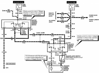
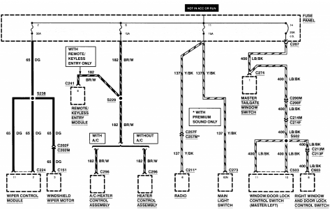
Here's the power supply diagram for power windows

download (39).png

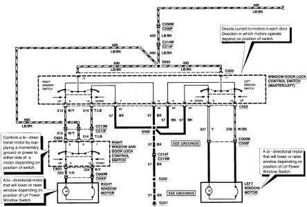
Here are the power windows system diagrams

download (40).png
download (41).png

If any door locks work, it's not a power supply.

If no door lock action, but power tailgate works, you might have a break at splice S502.

(Location S502 Window regulator left front door harness, near T/O to C500)

Translation:
Splice 502 is a 3 wire, light blue w/ black splice inside driver door that is found in harness close to window motor connector C500.

Your best testing is going to be right at driver switch with a test light. (Or power probe if you have one)
 

Members online

No members online now.

Latest posts

Forum statistics

Threads
22,516
Messages
135,945
Members
25,119
Latest member
Sgariffo
Top